Sealed prismatic battery connected via openings with conductive connection plates

a technology of connecting plate and prismatic battery, which is applied in the direction of cell components, cell grouping, cell component details, etc., can solve the problems of large component resistance, major barrier to the realization of higher power output or battery life improvement, and high cost, so as to reduce the internal resistance per cell, reduce the resistance between adjacent cells, and shorten the connection path

Inactive Publication Date: 2005-09-20
PANASONIC CORP +1
View PDF2 Cites 7 Cited by
  • Summary
  • Abstract
  • Description
  • Claims
  • Application Information

AI Technical Summary

Benefits of technology

[0010]The present invention has been devised in light of the problems in prior art described above, its object being to provide a sealed prismatic battery having lower internal resistance per cell and being capable of outputting higher power by ensuring that power generation of all the electrode plate groups is uniform.
[0019]With this structure, collectors of adjacent cells facing each other via the partition walls are connected together at a location in the side wall of the prismatic battery case via the pair of conductive connection plates that extend through the partition walls. Consequently, collectors can be connected together at a desired location, and the connection path is made shorter, whereby the connection resistance between adjacent cells is reduced. Also, the current distribution between adjacent cells is made even, which further reduces the internal resistance per cell and makes power generation of the electrode plate groups uniform, leading to higher power output. The connection between the conductive connection plates and collectors is readily achieved by connecting them at the openings formed in the side wall. The openings are tightly sealed after establishing the connection, so that no liquid leakage occurs.

Problems solved by technology

The cells are connected via a long connection path with many connection parts in this battery, resulting in large components' resistance.
In fact, the proportion of the components' resistance in such a battery to reaction resistance caused by the reaction between positive and negative electrode plates and liquid electrolyte in the battery was as high as 40 to 50%, and the high heat generation because of the large internal resistance was a major barrier to the realization of higher power output or improvement in battery life.
There was also the problem of high costs because of the large number of components required for the complex connection structure of the cells.
As a result, power generation of the electrode plate group 108 is not uniform, leading to power loss.

Method used


Image

  • Sealed prismatic battery connected via openings with conductive connection plates
  • Sealed prismatic battery connected via openings with conductive connection plates
  • Sealed prismatic battery connected via openings with conductive connection plates

Examples


Embodiment Construction

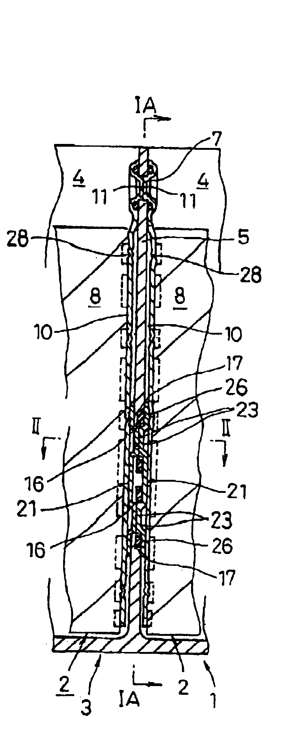
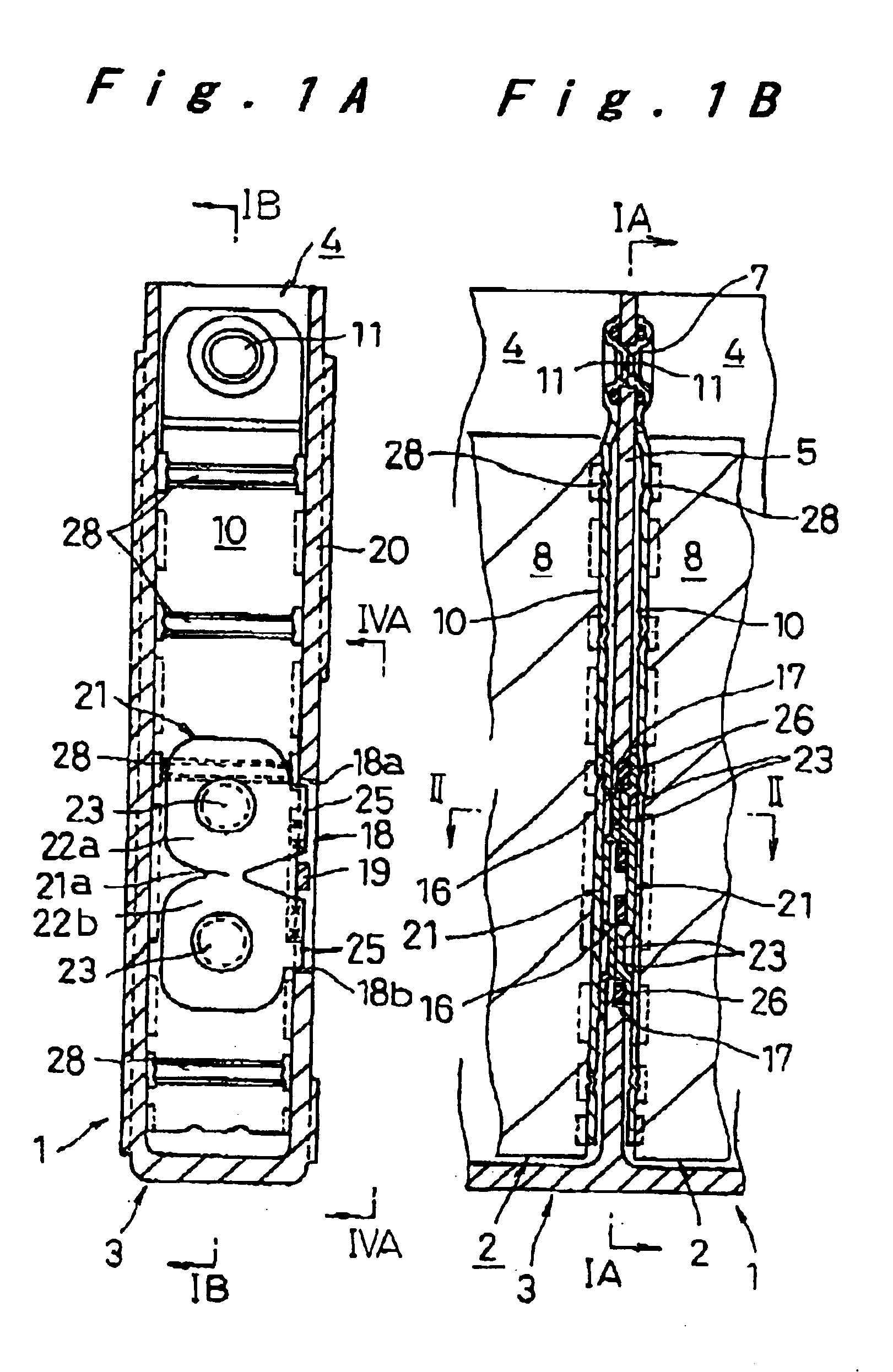
[0029]One embodiment of a sealed prismatic battery according to the present invention will be hereinafter described with reference to FIG. 1A to FIG. 4B.

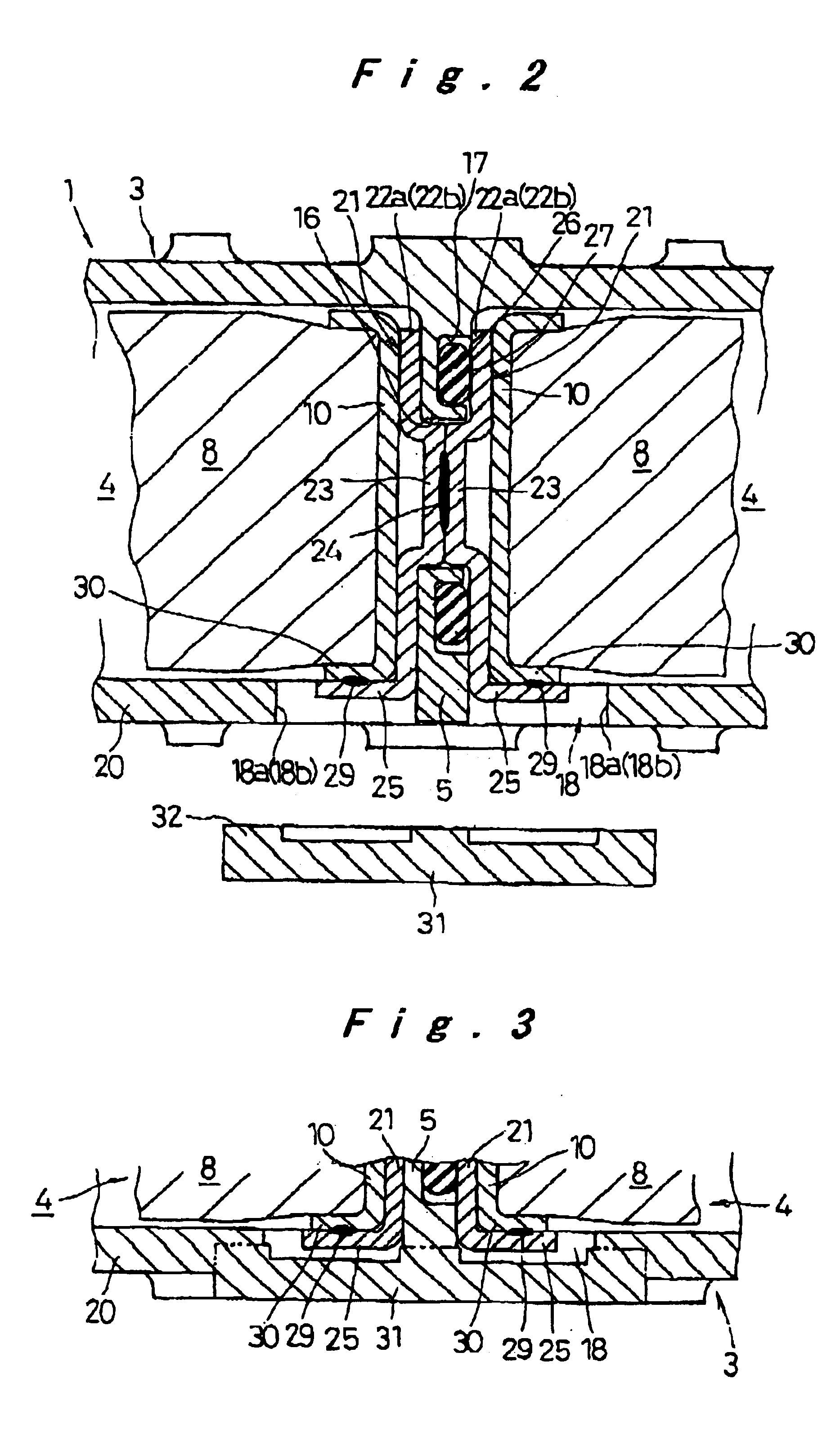
[0030]The sealed prismatic battery 1 of the present invention has a prismatic battery case 3 made of a plurality of prismatic cell cases 4, which have short lateral walls and long lateral walls and are connected together in such a manner that their short lateral walls are used as partition walls 5. The battery case 3 is made of synthetic resin such as a PP / PPE alloy which is repellent against liquid electrolyte. In the partition walls 5, connection holes 7 are formed in an upper part, and in addition, a pair of communicating holes 16 are formed at a suitable interval at upper and lower positions lower than the middle part. On one face of the partition walls 5 around these communicating holes 16 are formed sealing grooves 17.

[0031]In one side wall 20 of the battery case 3 is formed a pair of openings 18 at locations corresponding to ...


PUM

PropertyMeasurementUnit
conductiveaaaaaaaaaa
internal resistanceaaaaaaaaaa
power capacityaaaaaaaaaa

Abstract

A sealed prismatic battery having a battery case made of a plurality of prismatic cell cases coupled together via partition walls, electrode plate groups, and collectors bonded to lead portions on both sides of the electrode plate groups. In at least one side wall of the battery case is formed openings at locations corresponding to the partition walls such as to open to the cell cases on both sides of the partition walls. Pairs of conductive connection plates are connected to each other through the partition walls and formed with connection pieces that face the openings. The collectors are connected together via the conductive connection plates, i.e., they are connected to the connection pieces after the electrode plate groups are encased in the cell cases, and the openings are sealed by sealing plates in a manner that separates the cell cases.

Description

[0001]The present disclosure relates to subject matter contained in priority Japanese Patent Application Nos. 2002-9511 and 2002-196671, filed on Jan. 18, 2002 and Jul. 5, 2002, respectively, the contents of which is herein expressly incorporated by reference in its entirety.BACKGROUND OF THE INVENTION[0002]1. Field of the Invention[0003]The present invention relates to a sealed prismatic battery, and particularly to a prismatic battery module consisting of a plurality of cells with lower internal resistance.[0004]2. Description of Related Art[0005]One known rechargeable battery module consisting of a plurality of cells to achieve required power capacity has the following structure: The plurality of prismatic cells are arranged in parallel, with their longer lateral walls in contact with each other, and united by restraining bands together with end plates placed on the outer sides of the cells at the either end. Leads extending from the top ends of electrode plates of the cells upwa...

Claims


Application Information

Patent Timeline
Patent Type & Authority Patents(United States)
IPC IPC(8): H01M2/22H01M2/24H01M2/06H01M2/02H01M2/08H01M6/46H01M6/42H01M50/112H01M50/184H01M50/528H01M50/529H01M50/533H01M50/536H01M50/54
CPCH01M2/0242H01M2/08H01M2/24H01M2/266Y02E60/10H01M50/112H01M50/529H01M50/54H01M50/184H01M50/536H01M50/533
Inventor HAMADA, SHINJIETO, TOYOHIKOASAHINA, TAKASHI
Owner PANASONIC CORP
Why Eureka
Try Eureka