Eureka AIR delivers breakthrough ideas for toughest innovation challenges, trusted by R&D personnel around the world.

Electrical connector with multiple interfaces

a technology of electrical connectors and interfaces, applied in the direction of coupling contact members, coupling device connections, switchgear arrangements, etc., can solve the problems of large assembly size, difficult and time-consuming connection, and typically unsuitable assembly, so as to minimize the distance between the first and second ends, the connection pin can be shorter

Active Publication Date: 2014-02-27
THOMAS & BETTS INT INC
View PDF5 Cites 7 Cited by
  • Summary
  • Abstract
  • Description
  • Claims
  • Application Information

AI Technical Summary

Benefits of technology

The present invention provides an electrical connector with multiple interfaces. The connector has a body with two female interfaces and one male interface. It also has one or more side interfaces that are perpendicular to the longitudinal axis of the body. The connector can have different configurations with two or more side interfaces. The connector includes a connecting pin that is installed in the female connector and connected to the bus(es) of the interface. The connector is designed to minimize the distance between its ends. The technical effect of this invention is to provide a versatile electrical connector that allows for efficient and reliable connections in a wide range of applications.

Problems solved by technology

In tight spaces, this creates an issue since bolt on connectors are typically used, which require the use of tools to rotate male bushings into the female bodies of T-connectors.
In confined spaces, making these connections is difficult and time consuming.
However, they are typically unsuitable when the space available for the installation is limited.
This results in a relatively large assembly and requires additional space around the assembly to allow the user access to make the connection.

Method used


Image

  • Electrical connector with multiple interfaces
  • Electrical connector with multiple interfaces
  • Electrical connector with multiple interfaces

Examples


first embodiment

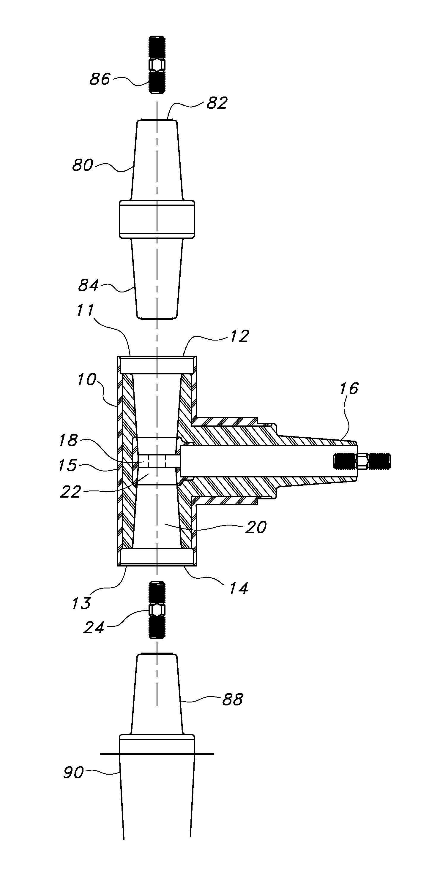
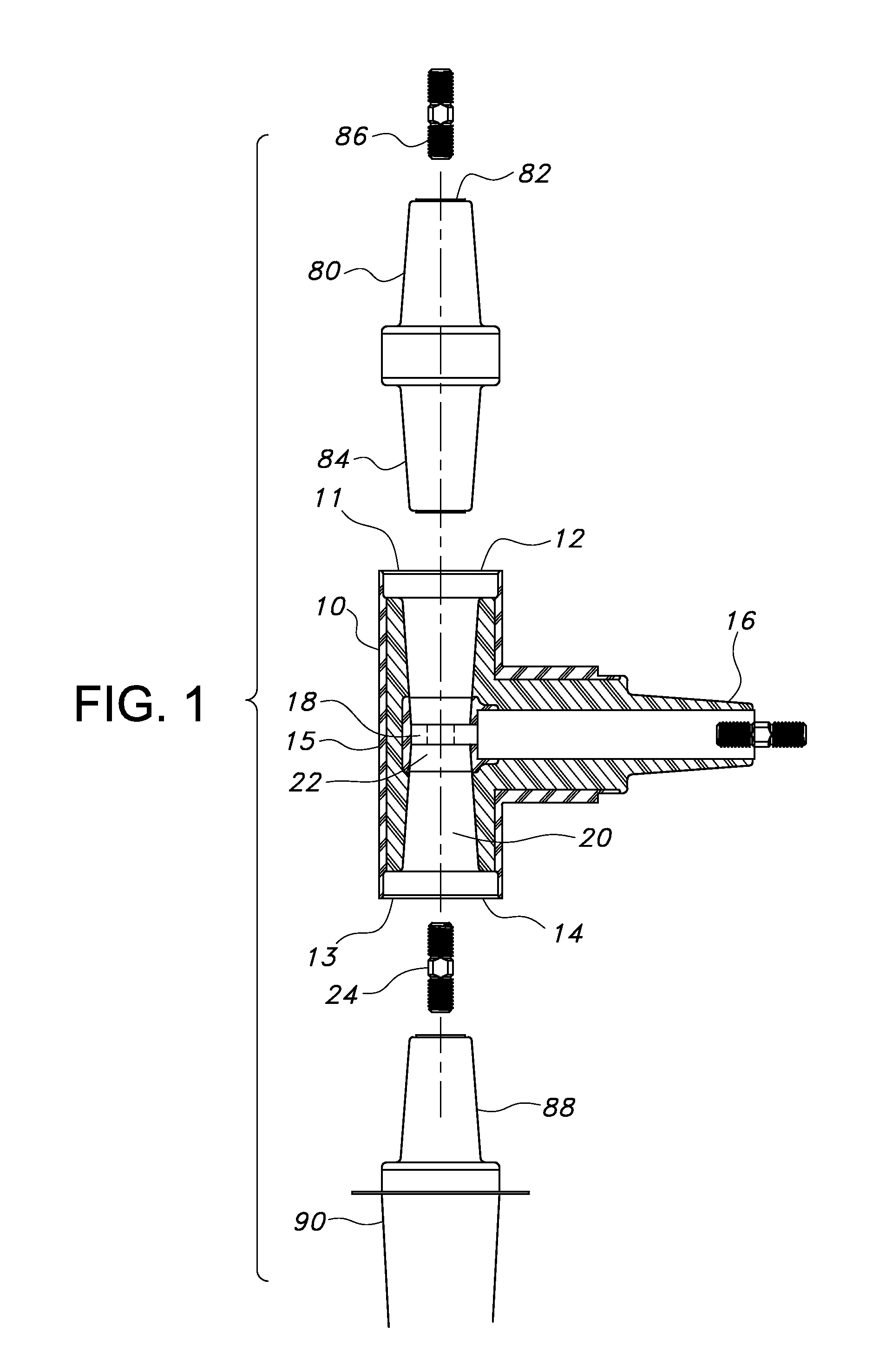
[0029]Referring now to the drawings, FIG. 1 shows an exploded side view of the electrical connector 10 has a body 15 with two female interfaces 12, 14 and a 600 amp male interface 16. A female connector 18 in the center of the passage 20 between the first and second ends 11, 13 of the electrical connector 10 has an aperture 22 for receiving a connector pin 24. As FIG. 1 illustrates, one of the female interfaces 12 of the electrical connector 10 can be connected to a connector plug 80 having two 600 amp male interfaces 82, 84. One of the male interfaces 82 of the connector plug 80 is connected to the electrical connector 10 and the other male interface 84 can use a connector stud 86 to make an additional connection. The other female interface 14 of the electrical connector 10 can be connected to a 600 amp male interface 88 on an apparatus bushing 90.

second embodiment

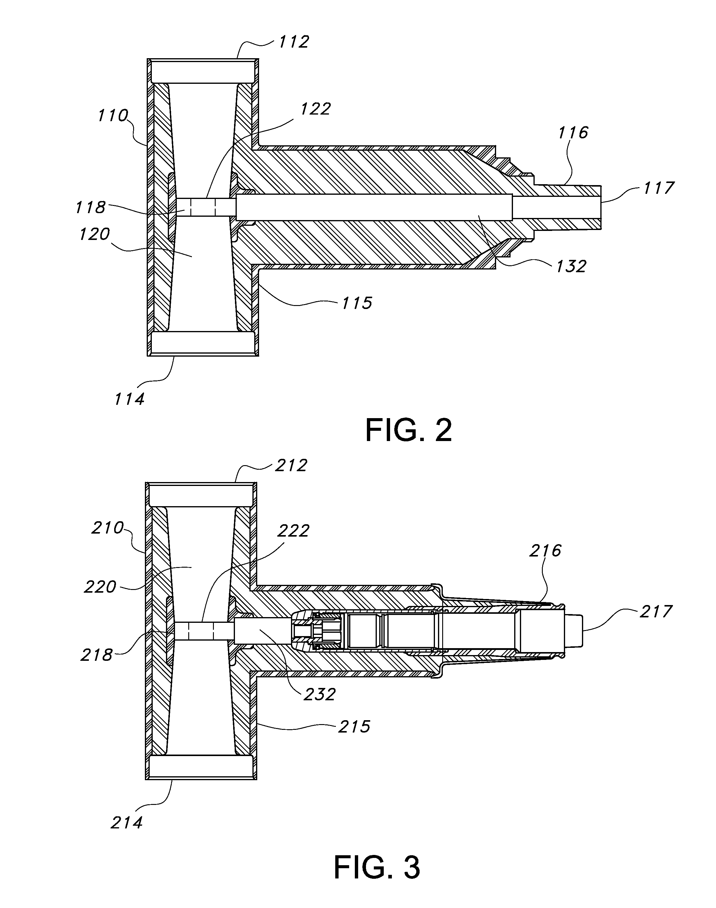
[0030]FIG. 2 shows the electrical connector 110 has a body 115 with two female interfaces 112, 114 on opposing ends of the passage 120 through the body and a side interface 116 for attaching 200 amp deadbreak elbow products. An electrical bus 132 extends from a female connector 118 with an aperture 122 located in the passage 120 to the distal end 117 of the side interface 116. The electrical connector 110 in FIG. 2 is the same as the electrical connector 10 in FIG. 1 except that the third (side) interface 116 is a 200 amp deadbreak connector.

third embodiment

[0031]FIG. 3 shows the electrical connector 210 has a body 215 with two female interfaces 212, 214 on opposing ends of the passage 220 through the body and a side interface 216 for attaching 200 amp loadbreak elbow products. An electrical bus 232 extends from a female connector 218 with an aperture 222 located in the passage 220 to the distal end 217 of the side interface 216. The electrical connector 210 in FIG. 3 is the same as the electrical connector 10 in FIG. 1 except that the third interface 216 is a 200 amp loadbreak connector.


PUM


Abstract

An electrical connector having a body, first and second female interfaces, a female connector, one to four side interfaces and a connecting pin. The body has a longitudinal axis with a passage extending between the first and second female interfaces. The side interfaces extend from the body and are substantially perpendicular to the longitudinal axis. The interfaces have a distal end and a bus electrically connected to the female connector. The ends of the connecting pin are adapted to snugly engage louver-type connectors on male interfaces, which are inserted into the first and second female interfaces. The electrical connector is designed to minimize the distance between the first and second ends of the body. The side interfaces of the electrical connector can be designed to accommodate different high voltage connectors.

Description

[0001]This application claims priority from provisional application Ser. No. 61 / 693,500, filed on Aug. 27, 2012, which is incorporated herein in its entirety.FIELD OF THE INVENTION[0002]The present invention is an electrical connector with multiple interfaces. In particular, the present invention relates to an electrical connector with multiple interfaces that can be used to connect electrical equipment in confined spaces.BACKGROUND OF INVENTION[0003]There is an increasing need by electrical power utility companies to install high voltage switchgear in smaller and smaller spaces. When two high voltage circuits need to be coupled, a connector is used to connect the circuit switchgear. In tight spaces, this creates an issue since bolt on connectors are typically used, which require the use of tools to rotate male bushings into the female bodies of T-connectors. In confined spaces, making these connections is difficult and time consuming.[0004]There are many prior art methods that use ...

Claims


Application Information

Patent Timeline
Patent Type & Authority Applications(United States)
IPC IPC(8): H01R25/00
CPCH01R25/006H01R13/17H01R13/53H02B13/005
Inventor SIEBENS, LARRY NORMAN
Owner THOMAS & BETTS INT INC
Why Eureka
Eureka Blog
Learn More