
Efficient polyphase filter having a compact structure

a polyphase filter and compact technology, applied in the field of efficient polyphase filter having a compact structure, can solve the problems of complex and large polyphase filter structure, parasitic capacitance associated with every node, attenuation of rf signal, etc., and achieve the effect of minimizing signal attenuation and minimizing parasitic capacitan

Active Publication Date: 2007-03-13
CSR TECH INC
View PDF6 Cites 7 Cited by
  • Summary
  • Abstract
  • Description
  • Claims
  • Application Information

AI Technical Summary

Benefits of technology

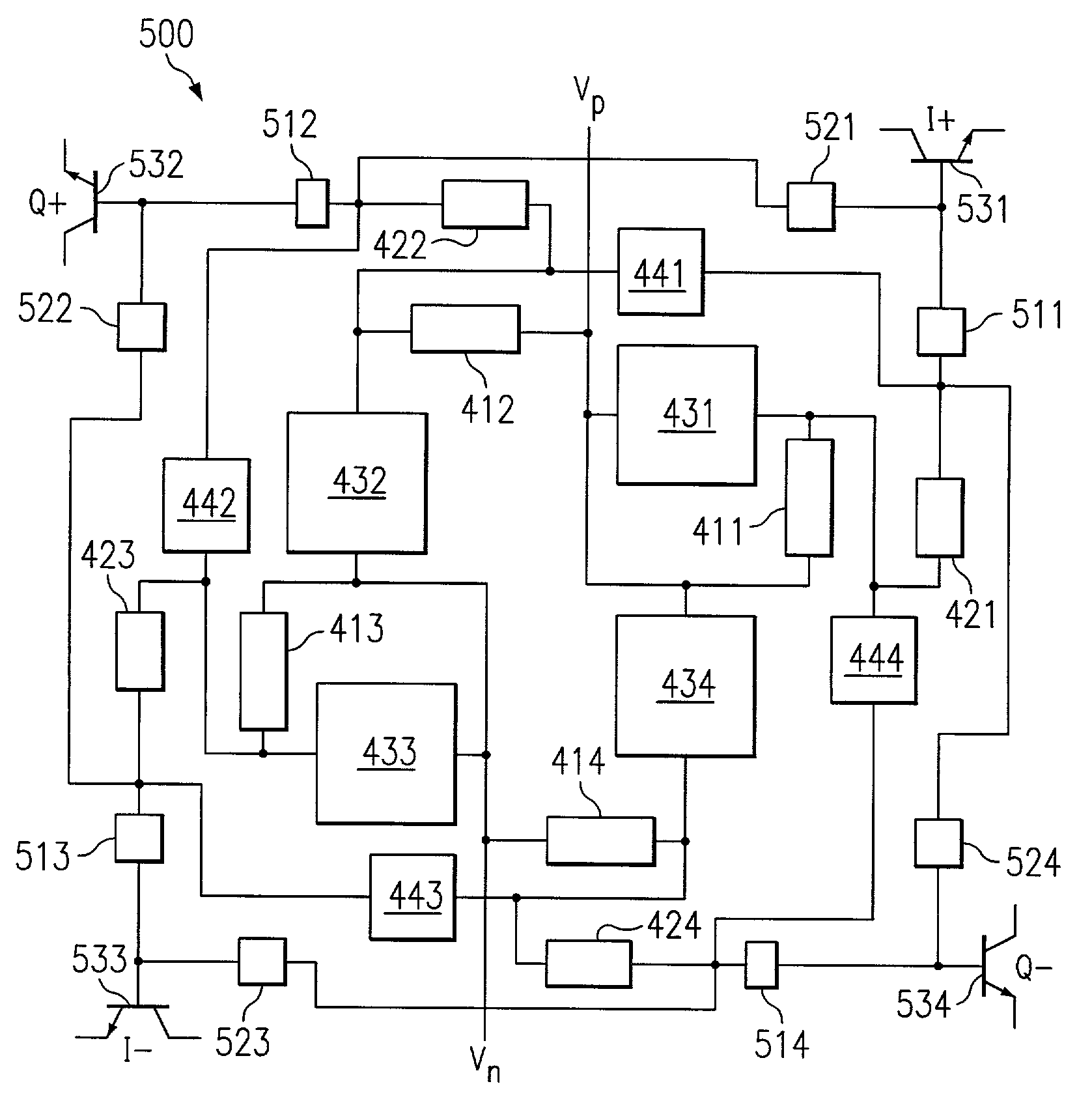
[0006]The present invention is directed to systems and methods which provide phase shifting of signals while minimizing signal attenuation associated with providing such phase shifting. A most preferred embodiment of the present invention provides a compact polyphase filter structure in which the geometry of the polyphase filter both minimizes parasitic capacitance and signal transmission paths therein.
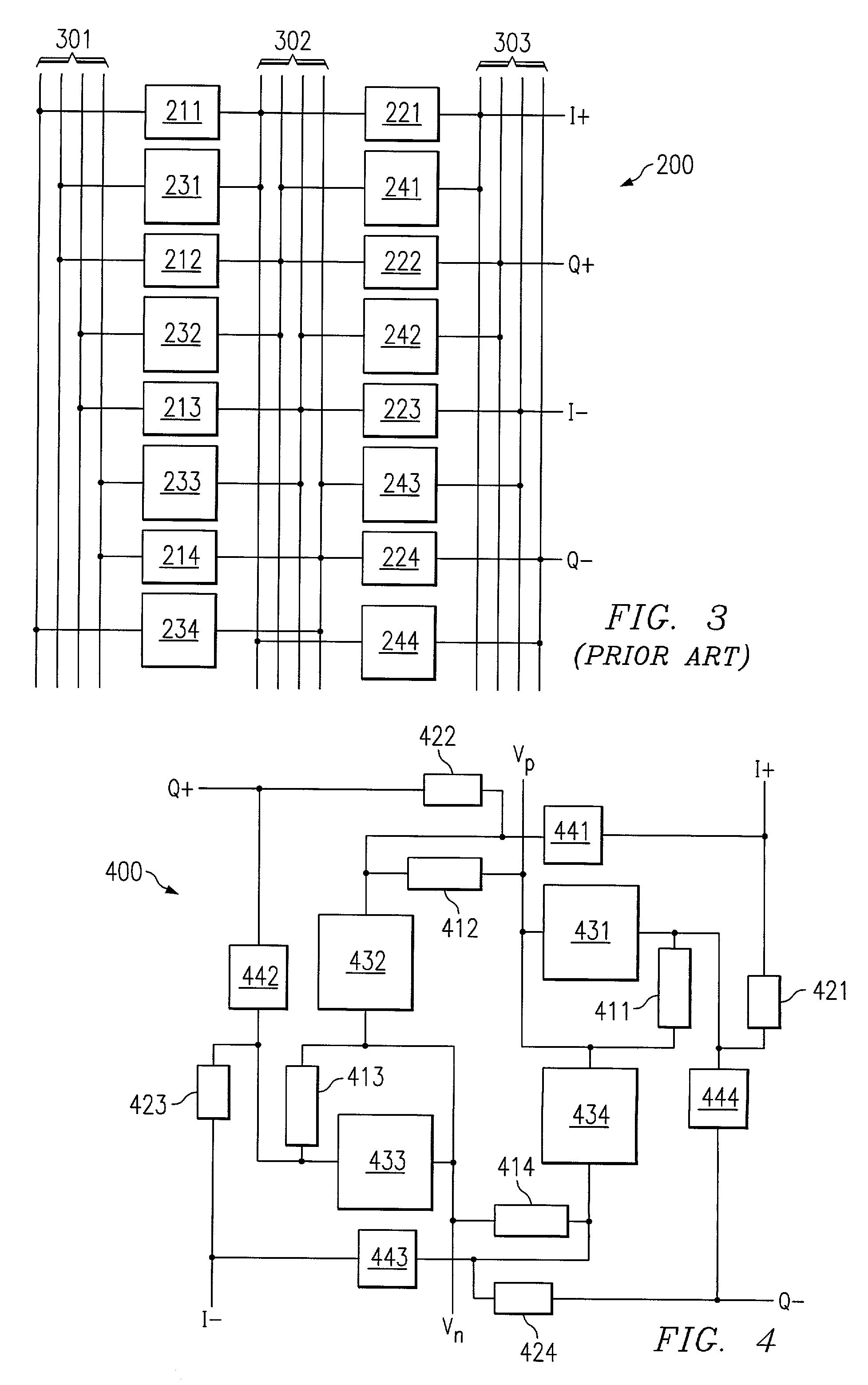
[0007]A preferred embodiment polyphase filter of the present invention utilizes a radial pinwheel structure. This preferred embodiment structure provides a geometry in which successive circuit components, e.g., resistors and capacitors, are disposed very near one another and in an orientation to accommodate very short connections therebetween. Accordingly, this embodiment of the invention does not require large routing signal paths going from component to component.
[0009]The preferred embodiment radial pinwheel polyphase filter structure provides several advantages over a typical polyphase filter structure. For example, the structure results in much less attenuation because the signal paths from device to device become much smaller. Additionally, such an embodiment provides synergism with respect to circuit geometry, facilitating a lay out in which parasitics are not only reduced but are also matched. Accordingly, preferred embodiments of the present invention have been able to provide phase shift differentials of 90° with respect to signals in the 2 GHz frequency range resulting in approximately 1 dB of attenuation associated with the polyphase filter circuit, as compared to approximately 7 dB of attenuation as is common with a typical prior art polyphase filter of conventional design.
[0010]An embodiment of the present invention includes the use of a buffer at the outputs of the polyphase filter circuit. For example, an emitter follower buffer may be placed at the 4 corners of a preferred embodiment pinwheel structure polyphase filter structure to provide buffering of the signals output therefrom. Such buffers may be utilized to reduce the amount of parasitics associated with the polyphase filter.

Problems solved by technology

However, there is parasitic capacitance associated with every node in such a circuit.
At high frequencies, parasitic capacitance will cause attenuation of an RF signal as it passes through the network.
Such matching concerns have typically been addressed in the prior art by providing excess signal path portions, thereby resulting in a complex and large polyphase filter structure.

Method used


Image

  • Efficient polyphase filter having a compact structure
  • Efficient polyphase filter having a compact structure
  • Efficient polyphase filter having a compact structure

Examples


Embodiment Construction

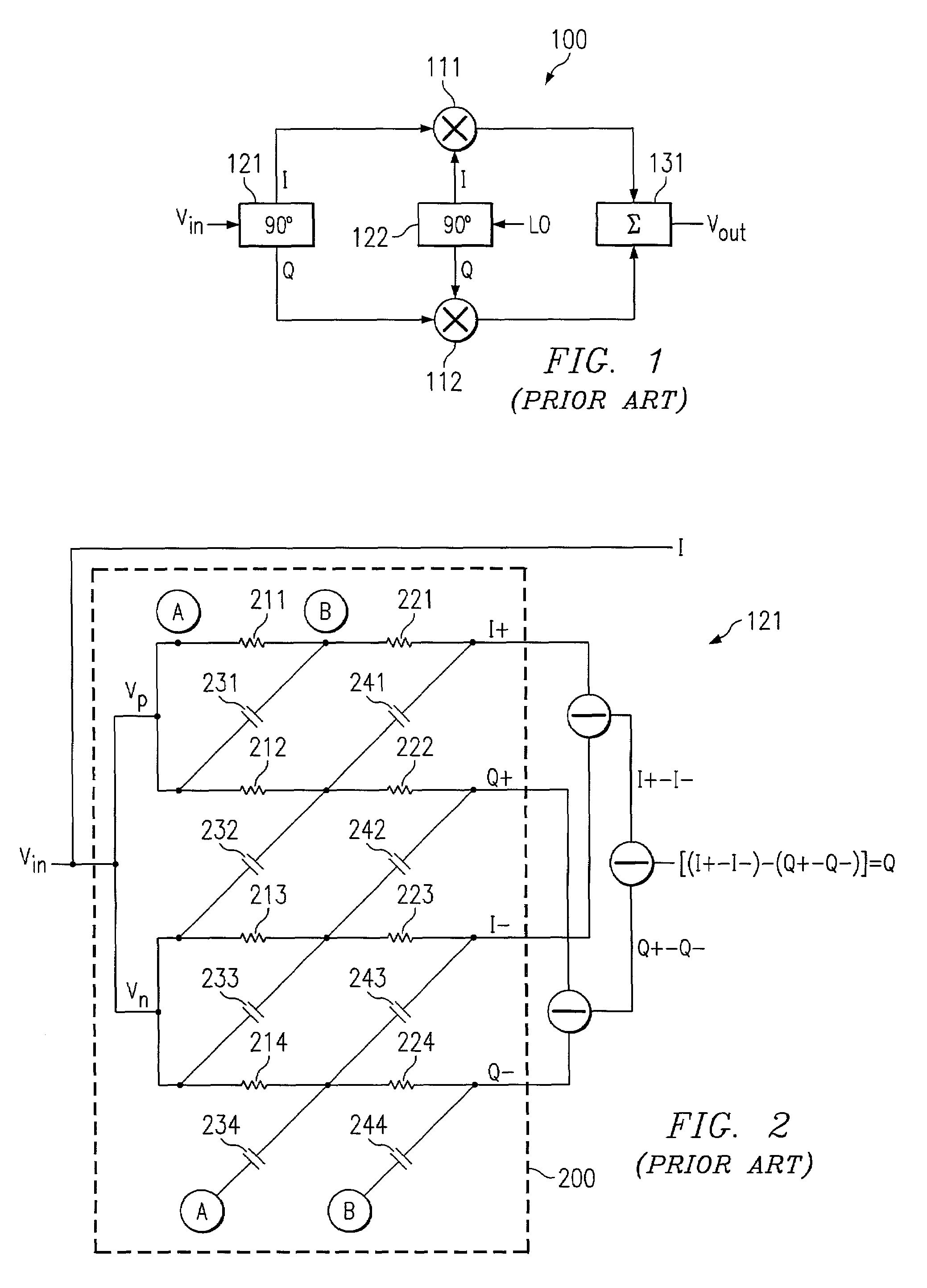
[0019]Directing attention to FIG. 1, a single sideband mixer is shown as mixer 100. As is well known in the art, a single sideband mixer utilizes 90° phase differentials to cancel a signal sideband and / or image associated with the mixing of signals of different frequencies. An input signal, here Vin having a first characteristic frequency, may be down-converted or up-converted to provide an output signal, here Vout having a second characteristic frequency, while undesired frequencies associated with the mixing of Vin with the local oscillator signal (LO) are canceled.

[0020]Accordingly, single sideband mixer 100 includes first 90° phase shifter 121 providing in-phase (I) and quadrature (Q) components of the input signal Vin. Similarly, second 90° phase shifter 122 provides I and Q components of the LO signal. Mixer 111 combines the I component of Vin with the I component of LO to thereby provide both fLO+fVin and fLO−fVin, wherein fLO is the characteristic frequency of the LO signal ...


PUM


Abstract

Disclosed are systems and methods which provide phase shifting of signals while minimizing signal attenuation associated with providing such phase shifting. Preferred embodiments provide a compact polyphase filter structure in which the geometry of the polyphase filter both minimizes parasitic capacitance and signal transmission paths therein. A polyphase filter of a preferred embodiment utilizes a radial pinwheel structure providing a geometry in which successive circuit components are disposed very near one another and in an orientation to accommodate very short connections therebetween. Embodiments may include the use of a buffer at the outputs of the polyphase filter circuit to reduce the amount of parasitics associated with the polyphase filter.

Description

BACKGROUND OF THE INVENTION[0001]It is often desirable to provide a controlled phase shift with respect to a signal. For example, radio frequency (RF) circuits often utilize 90° phase differentials with respect to a signal, e.g., in-phase (I) and quadrature (Q) signal components, to provide desired signal processing. One circuit using such 90° phase differentials is a single sideband mixer, typically using 2 90° phase shifters in order provide I and Q components with respect to a carrier signal and I and Q components with respect to a local oscillator (LO) signal. Through proper phase shifting and combining of the signals (destructive combining of undesired frequencies e.g., sidebands and / or images), such a single sideband mixer can be utilized to cancel undesired frequencies.[0002]To suppress undesired frequencies through destructive combining, the 90° phase differentials utilized by the single sideband mixer should be very accurate. Likewise, the amplitudes of the signal component...

Claims


Application Information

Patent Timeline
IPC IPC(8): H04B1/40H03H7/18
CPCH03H7/18
Inventor NISE, BENJAMIN E.
Owner CSR TECH INC
Learn More