
Mount for access point

Active Publication Date: 2019-09-17
JENSEN BJORN
View PDF7 Cites 0 Cited by
  • Summary
  • Abstract
  • Description
  • Claims
  • Application Information

AI Technical Summary

Benefits of technology

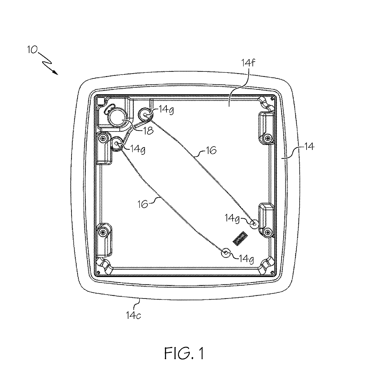
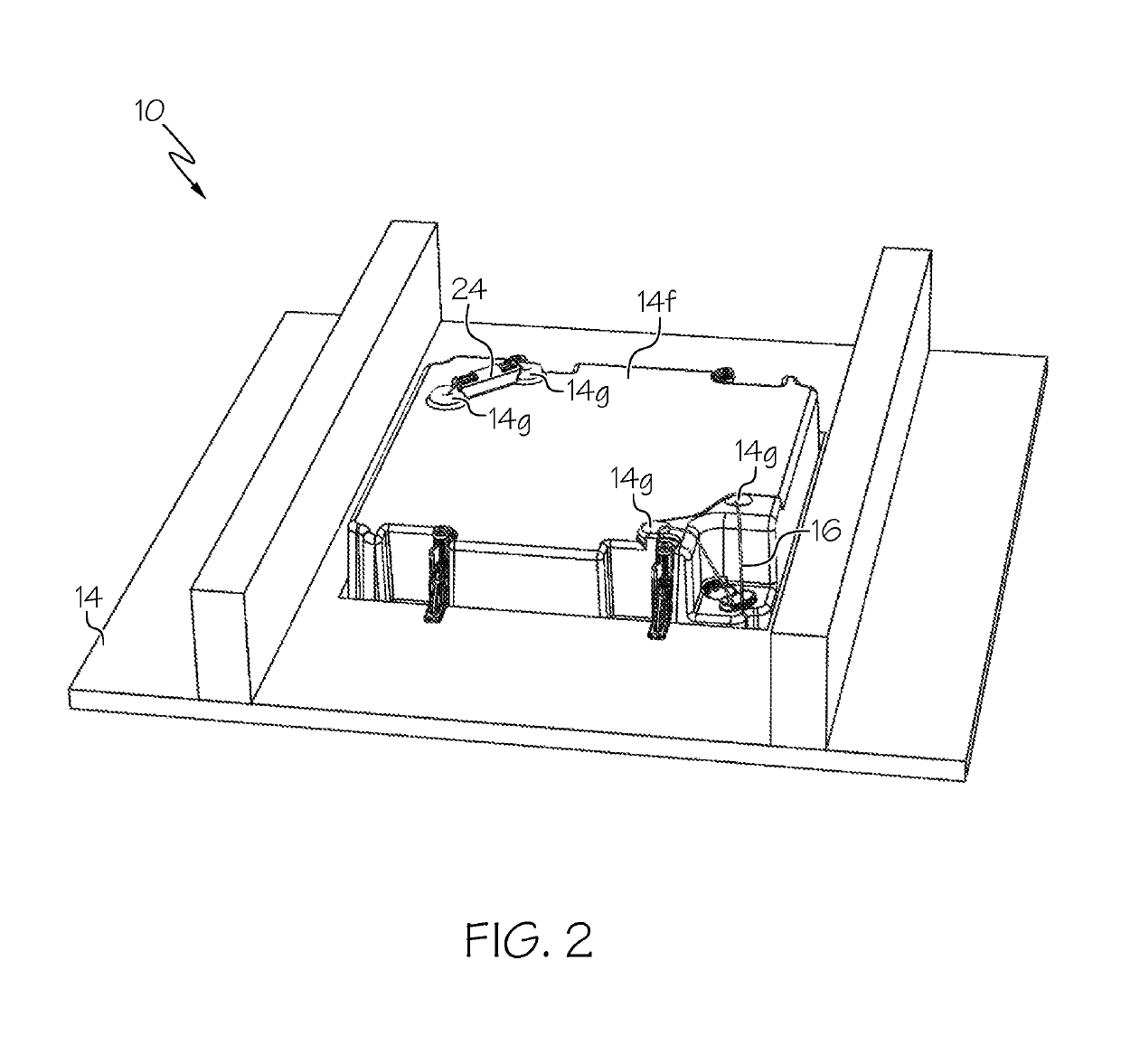
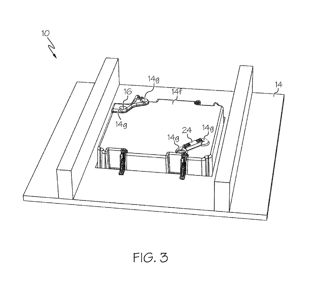
The invention is a mount that allows for the installation of a wireless access point (AP) in a ceiling or wall in a concealed and aesthetically acceptable manner. The mount includes a housing, a tension member for securely holding the AP, and a retention device for adjustable tension. The mount can also include a cover for concealing the AP. The mount optimizes signal strength and coverage in a room or area by avoiding installation behind walls and objects that can block signals. It provides quick and easy access for maintenance or replacement and can be mounted flush to the ceiling or wall for maximum signal coverage and strength throughout the room or area. The cable retention device allows for adjustable tension and easy removal of the AP. The mount allows for the AP to be installed in a way that maximizes signal strength and avoids installation in areas that may impair signal access.

Problems solved by technology

Walls, heavy furniture, and other objects may weaken, disrupt, or block such signals.
Therefore, positioning of the AP in a central location within a room or other area is desirable; however, such locations leave the AP visible, which may be undesirable for aesthetic purposes.
Alternatively, the AP may be concealed inside a closet, for example, a media closet, or within a cabinet; however, for the aforementioned reasons related to signal attenuation caused by transmission through walls or furniture, such positioning may also be undesirable.
Again, however, such positioning may be undesirable for aesthetic reasons because the AP will remain visible when installed on a wall or ceiling.

Method used


Image

  • Mount for access point
  • Mount for access point
  • Mount for access point

Examples


Embodiment Construction

[0054]The present invention is best understood by reference to the detailed drawings and description set forth herein. Embodiments of the invention are discussed below with reference to the drawings; however, those skilled in the art will readily appreciate that the detailed description given herein with respect to these figures is for explanatory purposes as the invention extends beyond these limited embodiments. For example, in light of the teachings of the present invention, those skilled in the art will recognize a multiplicity of alternate and suitable approaches, depending upon the needs of the particular application, to implement the functionality of any given detail described herein beyond the particular implementation choices in the following embodiments described and shown. That is, numerous modifications and variations of the invention may exist that are too numerous to be listed but that all fit within the scope of the invention. Also, singular words should be read as pl...


PUM


Abstract

A mount for attaching an access point (AP) device to a surface is described. The mount includes a housing, a tension member for securing the AP within a compartment of the housing, a retention device for securing the tension member to or about the housing with adjustable tension, and attachment means for securing the mount to or in the ceiling or wall. The tension member can be a cable and the retention device can be a cable retention device. The cable can include first and second ends attached to first and second ends of a spring that maintains tension on the cable even if the cable begins to relax over time while securing the AP within the compartment. The mount can also include a cover for concealing the AP within the housing. The cover, the housing, or both can include magnets for securing the cover to the housing.

Description

CROSS-REFERENCE TO RELATED APPLICATIONS[0001]This application is a nonprovisional application of and claims priority from U.S. provisional patent application Ser. No. 62 / 394,498 filed on Sep. 14, 2016. The foregoing applications are incorporated in their entirety herein by reference.FIELD OF THE INVENTION[0002]The invention relates to a mount for attaching a device to a surface. More particularly, the invention relates to a mount for attaching a wireless access point device to a ceiling or wall.BACKGROUND[0003]An access point (“AP”) is a networking hardware device for transmitting and receiving wireless signals to and from one or more wireless devices and a wired network, e.g., the Internet or a local area network. APs are often included as components of routers and provide wireless signals such as Wi-Fi used to connect wireless devices to a wired network. These hardware devices ideally are located in a position within a room or area space in such a way that signals transmitted to a...

Claims


Application Information

Patent Timeline
IPC IPC(8): H01J5/00H05K5/02H02B1/40H02G3/08H02G3/10H02G3/12H01L23/10H05K5/00H01R13/46H01R13/502H02G3/20
CPCH02B1/40H05K5/0204H02G3/086H02G3/12H01L23/10H05K5/0004H05K5/0052H02G3/08H02G3/10H05K5/02H05K5/00H02G3/20H02B1/38H02G3/081H02G3/123
Inventor JENSEN, BJORN
Owner JENSEN BJORN
Learn More