Electromagnetic borehole telemetry system incorporating a conductive borehole tubular

a technology of electromagnetic borehole and conductive borehole, which is applied in the direction of borehole/well accessories, instruments, surveys, etc., can solve the problems of inability to operate with a “hard wire” communication link, inability to direct or hard wire data telemetry, and difficulty in operation of hard wire communication links between borehole and surface transceivers, etc., to achieve negligible attenuation, increase electrode radial separation, and increase response sensitivity

Active Publication Date: 2006-10-24
WEATHERFORD TECH HLDG LLC
View PDF14 Cites 10 Cited by
  • Summary
  • Abstract
  • Description
  • Claims
  • Application Information

AI Technical Summary

Benefits of technology

[0014]Embodied to measure downhole electric field, one signal wire is electrically connected at one end to a casing connection terminal, again providing an electrode means positioned preferably near the bottom of the casing string. A second signal wire is electrically connected to the formation through an electrode at the borehole wall. This geometry radially displaces the two electrodes. Opposing ends of the signal wires are connected to corresponding signal terminals of the surface EM transceiver thereby yielding a measure of the radial component of the field. In another embodiment, an active field measuring means is disposed in the annulus defined by the outer surface of the casing and the borehole wall to measure a radial component of the field. In yet another embodiment, the second signal wire is electrically connected an electrode at the borehole wall so that it is displaced both radially and axially from the casing terminal electrode. With this geometry, the system responds to both radial and longitudinal components of the field. In another embodiment, the first signal wire electrode is not electrically connected to the casing, but disposed in the casing-borehole annulus. The second signal wire electrode is again electrically connected to the formation at the borehole wall. In yet another embodiment, the second signal wire electrode is penetrated into the formation thereby increasing electrode radial separation and increasing response sensitivity.
[0015]Assume first that the telemetry system is based upon a voltage measurement. Further assume that only one signal wire is electrically connected between a single casing connector terminal near the bottom of the casing string and a single surface EM transceiver terminal. EM transceiver ground terminal is connected to a remote ground by a by a ground wire. In the prior art, the EM signal is attenuated by intervening formation and borehole material between the surface and borehole EM transceivers. By using the signal wire, the transmitted EM signal is significantly attenuated only by intervening formation and borehole material between the borehole EM transceiver and the casing connection terminal located downhole. Because preferably a high impedance voltage measurement is now made at a point downhole on or beside the casing at the electrode means signal attenuation between the casing connection terminal and the surface EM transceiver is essentially eliminated. The high impedance voltage measurement that is preferably made causes very low or negligible current to flow in the signal wire, therefore, there is negligible attenuation within the signal wire. Stated another way, the effective distance between the surface and borehole EM transceivers is reduced. By utilizing the signal wire, overall signal attenuation is reduced significantly compared to attenuation of an EM signal transmitted directly between the borehole EM transceiver and the surface EM transceiver. Electromagnetic noise induced at or near the surface is also minimized since the signal wire is not attached at the surface, but is electrically connected to the casing downhole. In summary, the EM telemetry system is configured to minimize signal attenuation and to enhance signal-to-noise ratio. These features increase the depth within the borehole at which the telemetry system can operate efficiently.

Problems solved by technology

In many of the stage operations discussed above, it is not operationally feasible to use a “hard wire” communication link, such as one or more electrical or fiber optic conductors, between the borehole transceiver and the surface transceiver.
As mentioned above, direct or hard wire communication links for data telemetry are often operationally impractical in many well stage operations.
Hard wire communication links between the borehole and surface transceivers are operationally difficult because the downhole assembly containing the borehole transceiver is rotated typically by the drill string.
Data transmission rates are low using mud pulse systems.
Furthermore, the signal to noise ratio is typically small and signal attenuation is large, especially for relatively deep boreholes.

Method used


Image

  • Electromagnetic borehole telemetry system incorporating a conductive borehole tubular
  • Electromagnetic borehole telemetry system incorporating a conductive borehole tubular
  • Electromagnetic borehole telemetry system incorporating a conductive borehole tubular

Examples


Embodiment Construction

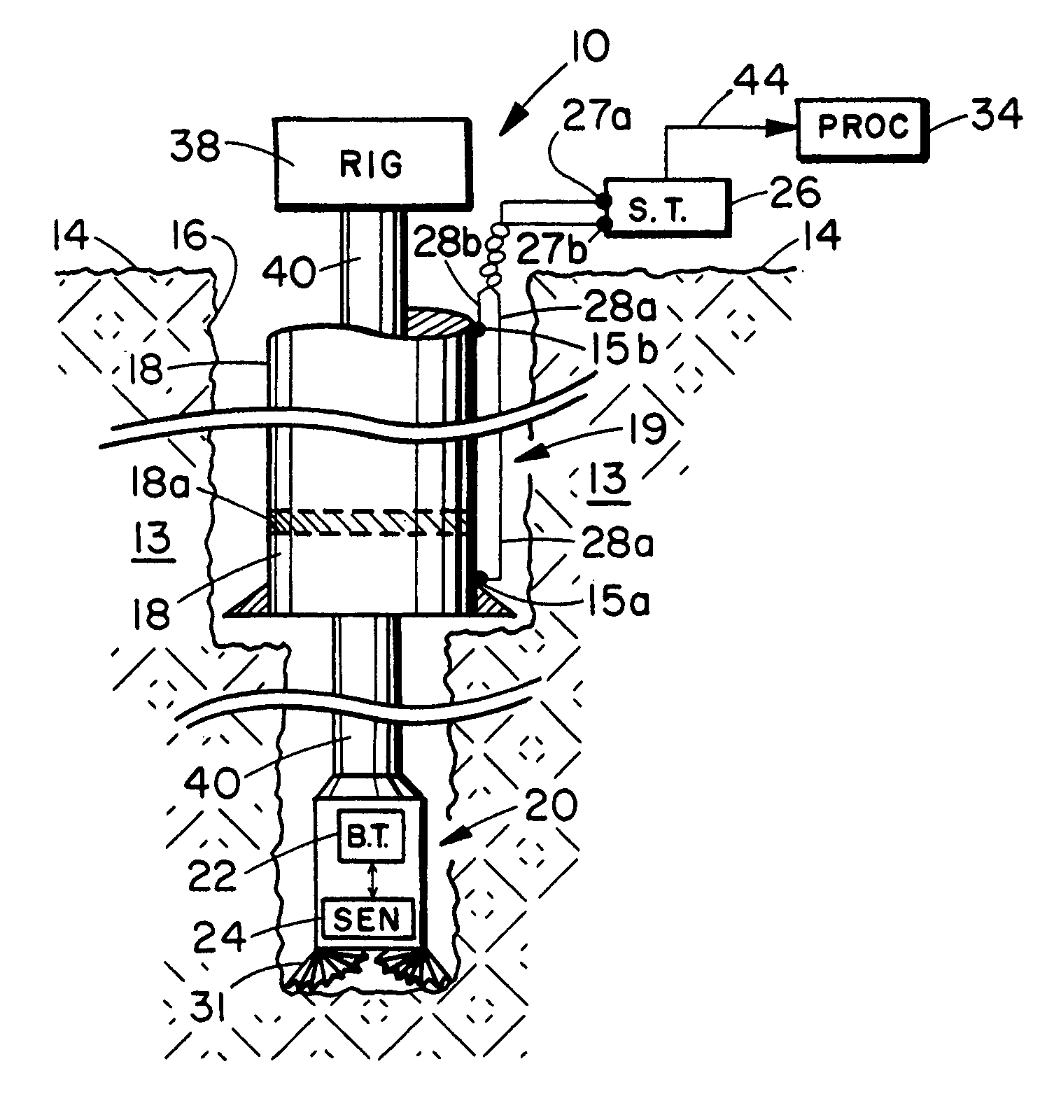
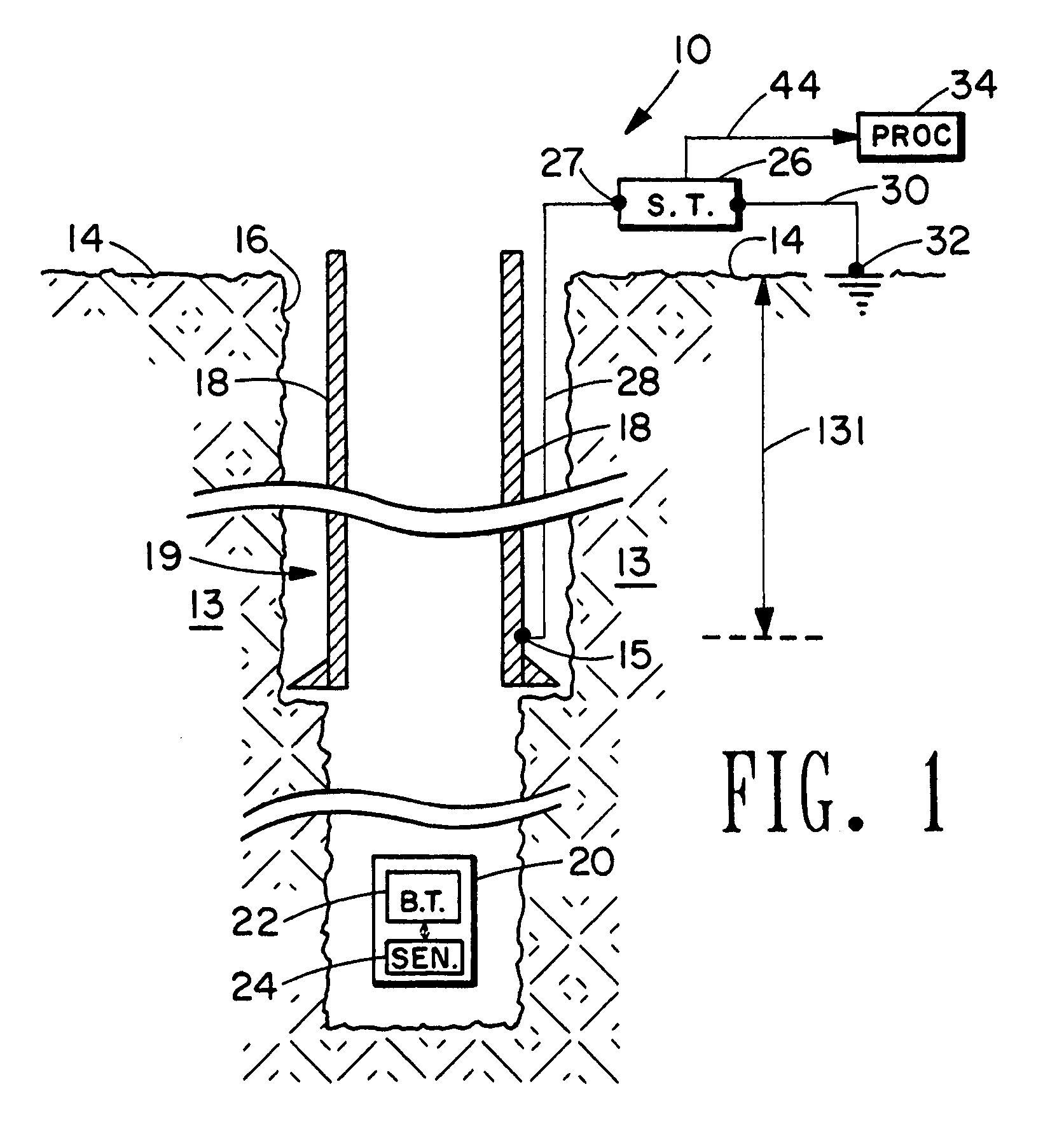
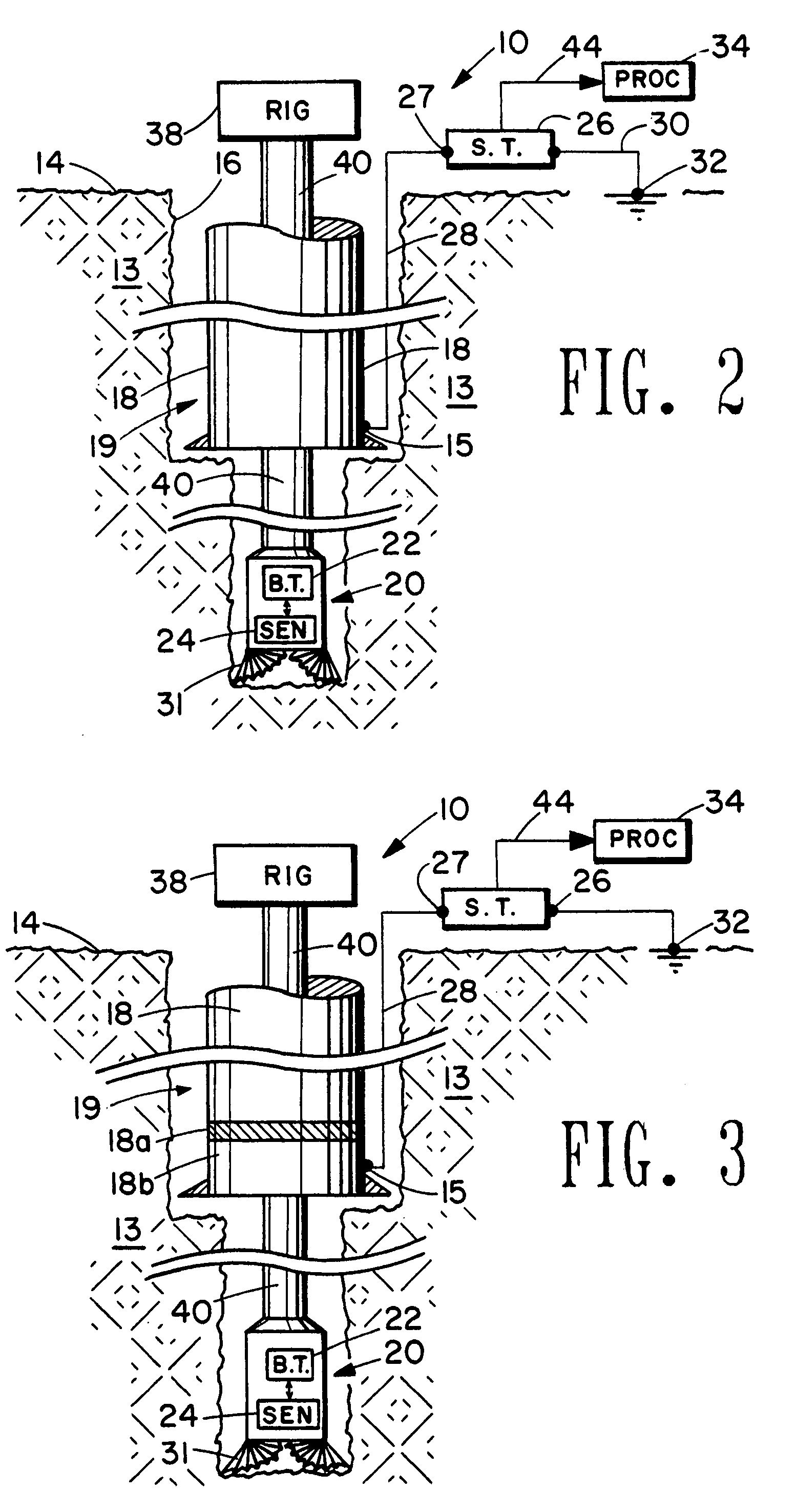
[0034]This present invention is directed toward an electromagnetic (EM) borehole telemetry system for transmitting information between a “borehole” EM transceiver, disposed preferably within a downhole assembly in the borehole, and a “surface” EM transceiver at or near the surface of the earth. It is noted that the “surface” EM transceiver need not be located on the surface of the earth, but it is always disposed above or “up-hole” with respect to the borehole EM transceiver. The telemetry system configured to measure downhole voltage and downhole field will be discussed separately in the following sections.

Downhole Voltage Measurement

[0035]FIG. 1 is a conceptual illustration of the basic elements of the invention, which is identified as a whole by the numeral 10. The system 10 operates at a low frequency, typically in the frequency range less than 100 Hertz (Hz). A string of conductive tubular, such as steel casing, is shown disposed within a borehole 19 penetrating earth formation...


PUM


Abstract

An electromagnetic borehole telemetry system for transmitting information between a borehole transceiver and a surface transceiver located at or near the surface of the earth. Tubulars, such as steel casing and liners, are typically set within the well borehole to stabilize the wall of the borehole and to assist in hydraulically isolating penetrated formations. The invention utilizes these tubulars cooperating with one or more signal wires to reduce attenuation and noise in signals transmitted between the borehole and surface transceivers. The one or more signal wires are typically disposed within an annulus formed by the borehole wall and the outside surface of the casing. The one or more signal wires are connected at one end to one or more connection terminals positioned preferably near the bottom a tubular string. Opposing ends of the one or more signal wires are connected to one or more terminals of the surface transceiver. By minimizing signal attenuation and noise, the telemetry system can be effectively used at greater depths in the borehole. The telemetry system can be embodied in a measurement-while-drilling system, a formation testing system, a production monitoring system and other system requiring communication between a downhole assembly and the surface of the earth.

Description

[0001]This application is a continuation-in-part of application Ser. No. 10 / 649,431 filed on Aug. 27, 2003.[0002]This invention is directed toward an electromagnetic borehole telemetry system for transmitting information between a borehole transceiver and a transceiver at or near the surface of the earth. More specifically, the invention is directed toward an electromagnetic telemetry system which uses a signal wire cooperating with conductive tubular within the borehole to reduce signal attenuation and enhance signal to noise ratio thereby increasing the depth within the borehole at which the telemetry system can operate efficiently. The borehole transceiver cooperates with one or more sensors, and is typically disposed in a downhole assembly used to drill a borehole, to measure drilling and formation parameters, to test potential of a well borehole penetrating a hydrocarbon bearing formation, or to monitor production of a hydrocarbon or other fluid producing well.BACKGROUND OF THE...

Claims


Application Information

Patent Timeline
Patent Type & Authority Patents(United States)
IPC IPC(8): G01V3/00E21B17/00E21B47/12G01V11/00
CPCE21B17/003E21B47/122G01V11/002E21B47/13
Inventor WISLER, MACMILLAN M.HALL, JR., HUGH E.WEISBECK, DENIS
Owner WEATHERFORD TECH HLDG LLC
Why Eureka
Try Eureka