Portable telephone with flap hinged to its casing

Inactive Publication Date: 2004-03-09
DRNC HLDG INC
View PDF23 Cites 29 Cited by
  • Summary
  • Abstract
  • Description
  • Claims
  • Application Information

AI Technical Summary

Benefits of technology

The object of the invention is theref

Problems solved by technology

Because this intermediate position of the flap during a call is uncomfortable for the user, it automati

Method used


Image

  • Portable telephone with flap hinged to its casing
  • Portable telephone with flap hinged to its casing
  • Portable telephone with flap hinged to its casing

Examples


Embodiment Construction

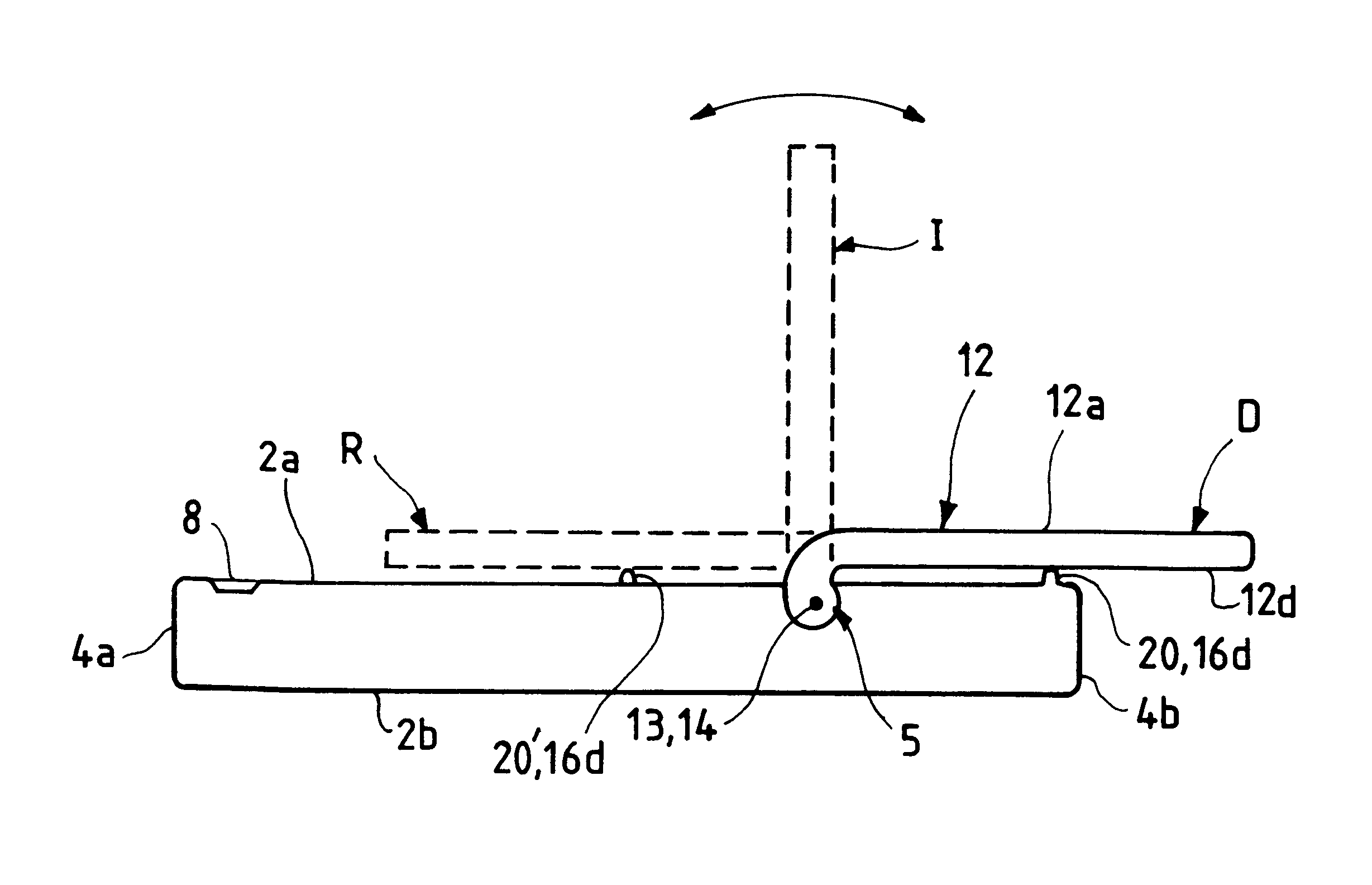
The portable telephone shown in the figures is a mobile telephone. The invention encompasses any radio telephone appliance for hands-free use, i.e. providing the telephone mode referred to as the "hands-free" mode.

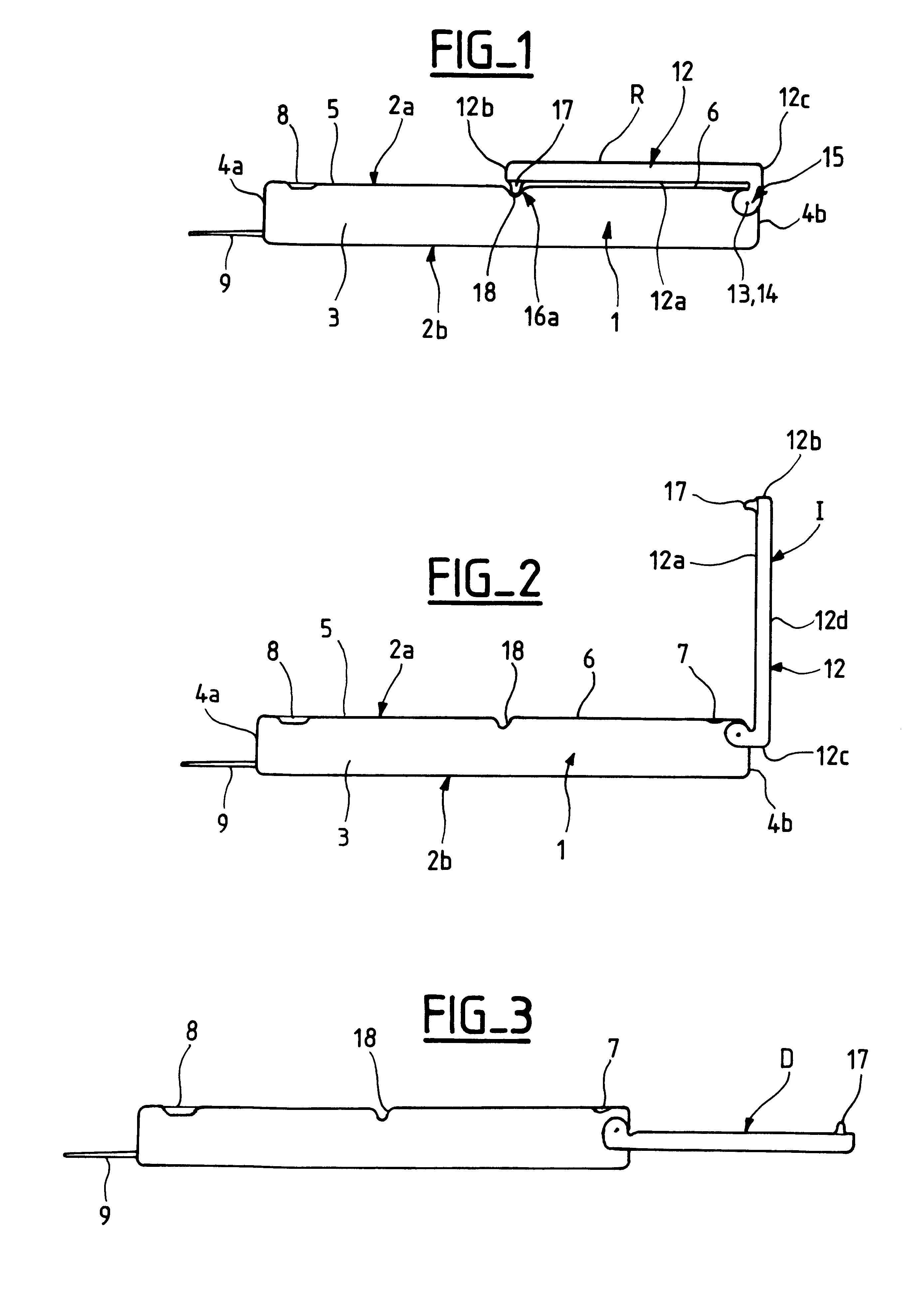
The telephone has a generally rectangular casing 1 with two substantially parallel large faces, namely a front face 2a and a rear face 2b. The front and rear faces 2a, 2b are connected together by two opposite side faces 3 and by top and bottom faces 4a and 4b.

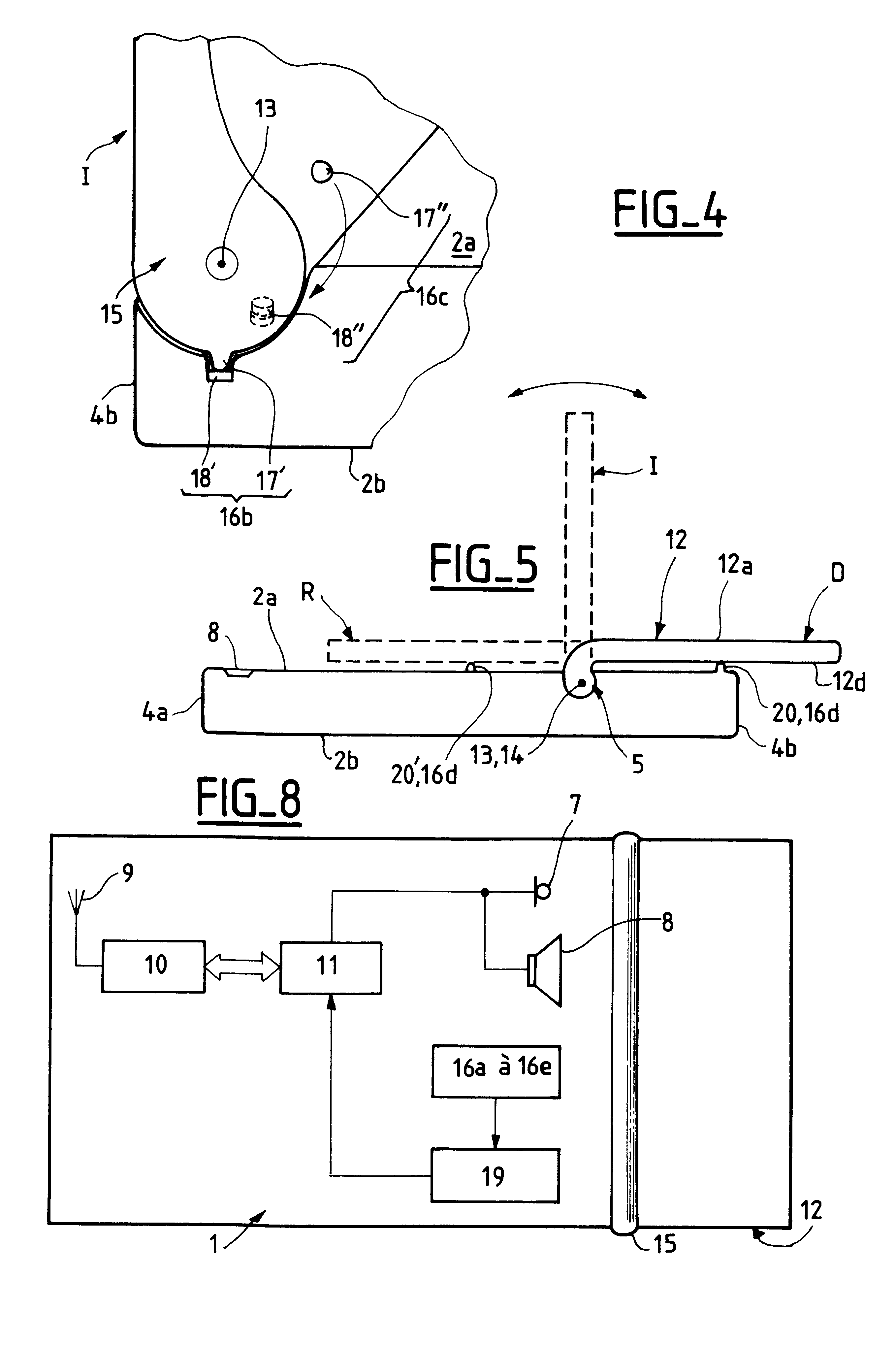
The front face 2a includes a screen 5, an alphanumeric keypad 6, a microphone 7 near the bottom face 4b, and a loudspeaker 8 near the top face 4a.

The telephone also includes an antenna 9 which can be inside or outside the casing 1, and a radio circuit 10 inside the casing 1 (see FIG. 8).

The radio circuit 10 is connected to a control circuit 11, usually a microprocessor.

When it receives radio signals, the antenna 9 converts them into electrical signals to be processed by the radio circuit 10. The data corresponding to...


PUM


Abstract

A portable telephone including a casing, a flap pivotable relative to the casing, the flap being able to assume a retracted position, a deployed position and an intermediate position. The telephone also includes means for sensing the position of the flap and a switch connected to the sensing means. The switch includes means for selecting an "off-hook" mode when the flap is in the retracted position or an "on-hook" mode when the flap is in the retracted position or a "hands-free" mode when the flap is in an intermediate position.

Description

The invention relates to a portable telephone having a casing and a flap pivotable relative to the casing.The flap can assume various angular positions relative to the casing between two extreme positions:a retracted position, in which the flap is retracted against the casing, for example to cover an alphanumeric keypad; anda deployed position, in which the flap is at an angle of substantially 180.degree. to the casing.The flap generally protects the keys in the retracted position and allows access to them in the deployed position.The portable telephone also includes means for sensing the position of the flap and a switch connected to the sensing means to select an "off-hook" mode enabling a telephone call to be conducted when the flap is in the retracted position or an "on-hook" mode interrupting the telephone call in progress when the flap is in the retracted position.The expression "portable telephone" refers to any type of cordless telephone, for example telephones which are con...

Claims


Application Information

Patent Timeline
IPC IPC(8): H04M1/02H04M1/60H04M1/06H04W88/02
CPCH04M1/0216H04M1/0243H04M1/605H04M2250/12
Inventor HIEBEL, CLAUDE
Owner DRNC HLDG INC
Why Eureka
Try Eureka