Method and apparatus for producing fluid cavitation

a technology of fluid cavitation and cavitation chamber, which is applied in the direction of fluid removal, cleaning apparatus, borehole/well accessories, etc., can solve the problems of difficult to obtain cavitation rate, high cost, and inability to produce fluid cavitation

Inactive Publication Date: 2004-03-16
BIP TECH
View PDF11 Cites 52 Cited by
  • Summary
  • Abstract
  • Description
  • Claims
  • Application Information

AI Technical Summary

Problems solved by technology

It follows that too high fluid pumping rate is required to provide a rupture of a flow continuity which rates are difficult to obtain, especially in deep wells or long pipelines;
2. It appears to be impossible to obtain cavitation due to such devices at high hydrostatic pressure values, for example in deep wells.
1. Ball closes less than 0.8 of the cross-section area of the conduit and is motionless, and therefore either very high fluid pumping rates or the corresponding narrowing of the conduit (as it is usually employed in hydrodynamic setups to model th...

Method used


Image

  • Method and apparatus for producing fluid cavitation
  • Method and apparatus for producing fluid cavitation
  • Method and apparatus for producing fluid cavitation

Examples


first embodiment

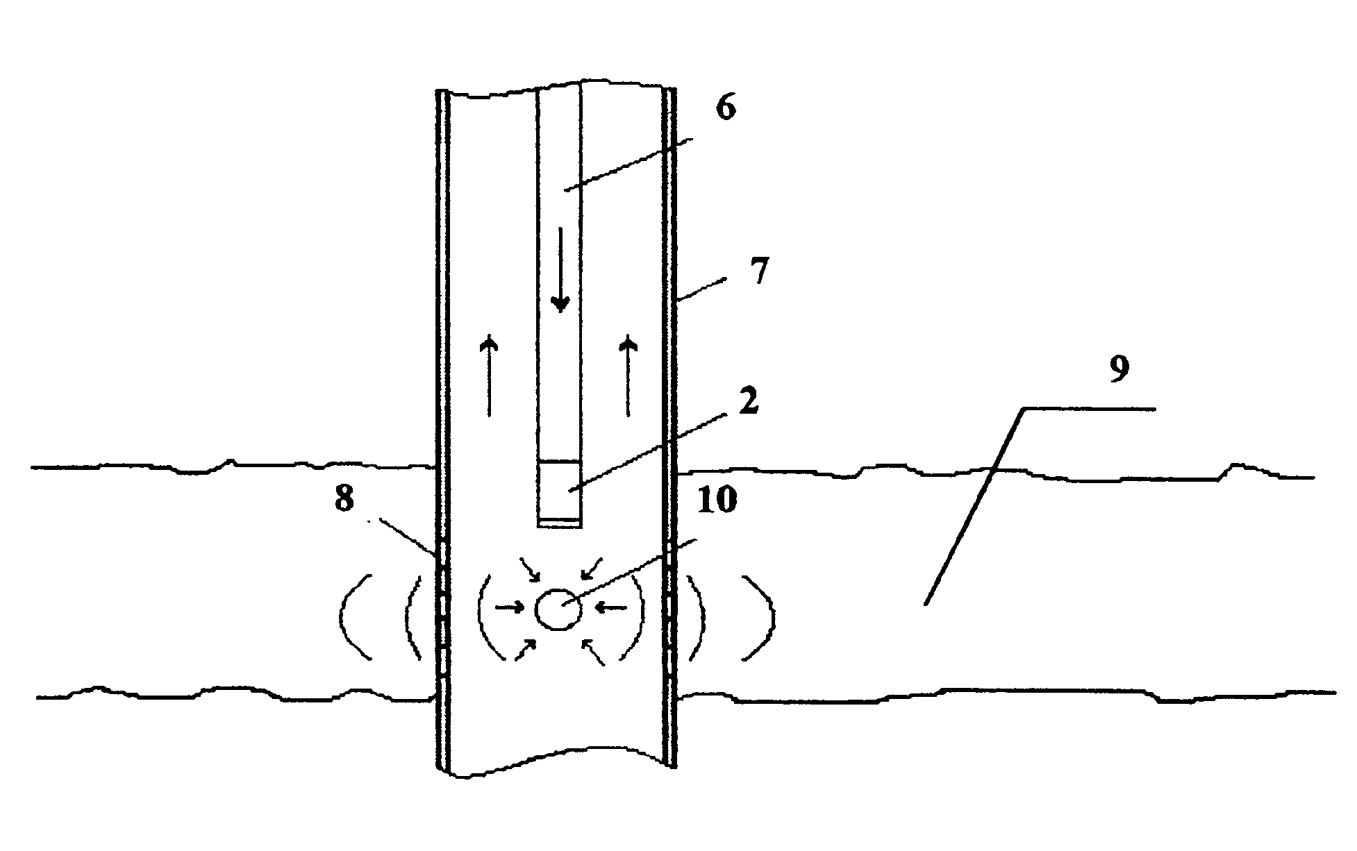
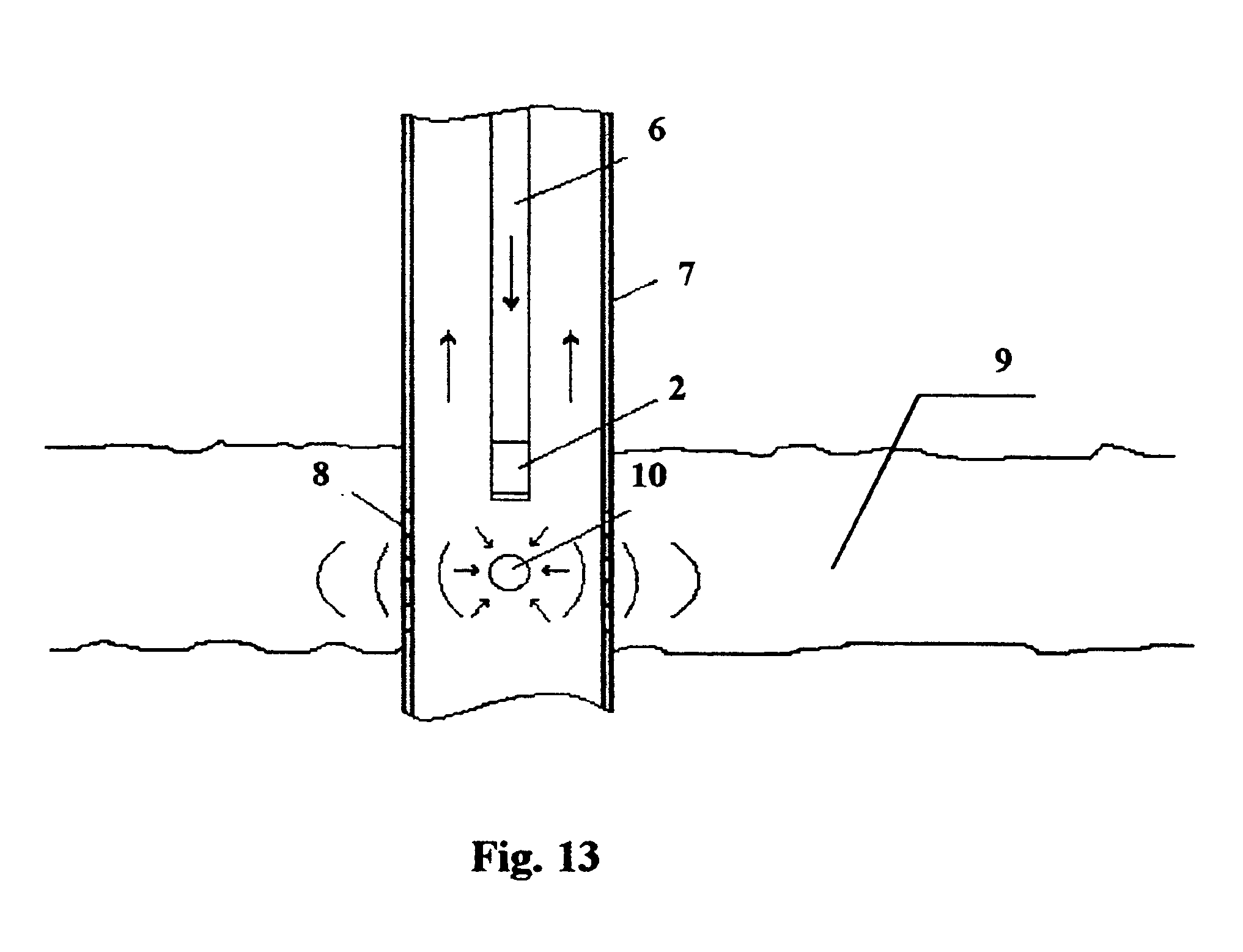
In the first embodiment, a casing of a said device was mounted at the bottom end of tubing and then descended with it into a well to a perforation depth. After washing the well off a ball of a correspondent diameter was dropped into an inner space of the tubing column. Fluid was pumped until the ball is set on a support restricting further axial motion within the device casing. Then the hydraulic pumps were connected to a tubing column to provide pumping rate sufficient to operate the device. The treatment of the rock was continued during 6 hours at a pumping rate of Q=20 liters per second. The estimated pulse repetition rate was 4800 Hz.

The results of treatment are as follows: oil inflow rate was increased by 2.6 times.

second embodiment

In the second embodiment used for rotor drilling a bit sub was mounted above the bit and inside of which a cone shaped cavitator was placed. The goal of the test was to estimate the effect of the cavitational regime of washing on effectiveness of breaking the rock by a rolling cutter drill bit. The drilling was carried out at a depth of 1624-1950 meters through the monotypic argillite packs at a weight on the bit of 18 tons. Bit rotation was 65 rpm, pumping rate was 30-35 liters per second. A clayey drilling fluid was used of 1.17 g / cub.cm by gravity and viscosity of 30 sec as measured using a SPV-5 cone.

The results of the claimed method implementation in comparative conditions are as follows: the life of drill bit was extended from 168 meters to 319 meters and drilling rate was increased from 1.65 meters per hour to 3.5 meters per hour.


PUM


Abstract

A method and apparatus for producing fluid cavitation is provided. For a given channel cross-section of a pressure line, the flow is accelerated so as to reach a speed at which Re>Recr, where Re is the Reynolds number and Recr is the critical Reynolds number; the flow is then interrupted for a time less than half of the phase of the hydraulic shock. The device for cavitation of fluid flow is mounted in the channel of a pressure line and includes a cavitator which has the form of a working body placed in the casing and can move radially inside the line and, to a limited extent, along the axis of the line. The maximum cross-section surface of the working body in a plane perpendicular co the axis of the line is more than 0.8 of the passage of the line but not equal to it.

Description

This invention pertains to hydrodynamics predominantly related to an oil and gas industry and also this invention can be used for other purposes such as eliminating of microbiological objects, cleaning of surfaces from deposits, erosive breaking (pitting) of metals, promoting of chemical reactions, dispersing of solid particles or high molecular compounds into liquid, making emulsions of non-soluble compounds, and in other processes to improve effectiveness of internal mass transfer.PRIOR ARTA method of cavitation of a liquid is known (I. S. Pearsall, Cavitation, Mills & Boon Ltd., London, 1972, pp. 9-16) which is referred to as vibrational method. It comprises an oscillating body (for example, a magnetostriction vibrator) that generates waves of pressure and decompression in the ambient fluid. At certain magnitude of acceleration (oscillation frequencies) the pressure during the decompression phase reduces down to atmospheric thus providing a rupture of the fluid continuity and a c...

Claims


Application Information

Patent Timeline
IPC IPC(8): E21B7/18E21B37/08E21B28/00E21B37/00F15D1/02F15D1/00
CPCE21B7/18E21B28/00E21B37/08F15D1/02
Inventor IVANNIKOV, VLADIMIR IVANOVICHIVANNIKOV, IVAN VLADIMIROVICH
Owner BIP TECH
Why Eureka
Try Eureka