Apparatus for artificial reef

a technology of artificial reefs and apparatuses, applied in applications, pisciculture and aquaria, climate change adaptation, etc., can solve the problems of phytoplankton consumption of carbon dioxide, inserts corrode, phytoplankton cannot disclose the unique features of the present,

Inactive Publication Date: 2004-03-30
HALL JOHN W
View PDF10 Cites 24 Cited by
  • Summary
  • Abstract
  • Description
  • Claims
  • Application Information

AI Technical Summary

Problems solved by technology

However, none of the prior art devices disclose the unique features of the present.
In use, the inserts corrode to promote rapid phytoplankton growth.
Additionally the phytoplankton consumes carbon dioxide during the rapid growth.
Additionally, the flutes of one sheet may have a different height from the flutes of an adjacent sheet, thereby adding to the complexity of the passage system.

Method used


Image

  • Apparatus for artificial reef
  • Apparatus for artificial reef
  • Apparatus for artificial reef

Examples


Embodiment Construction

)

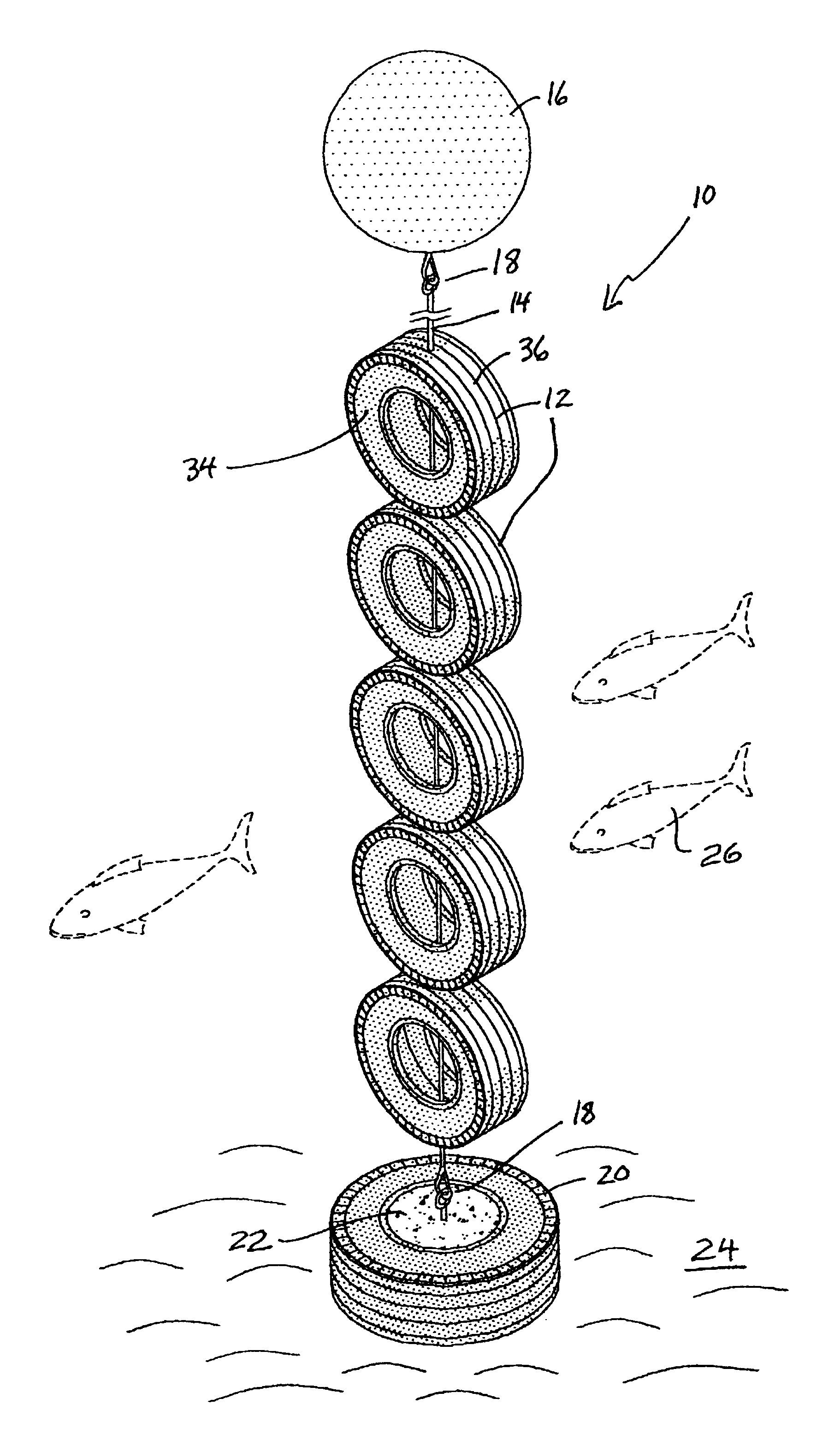
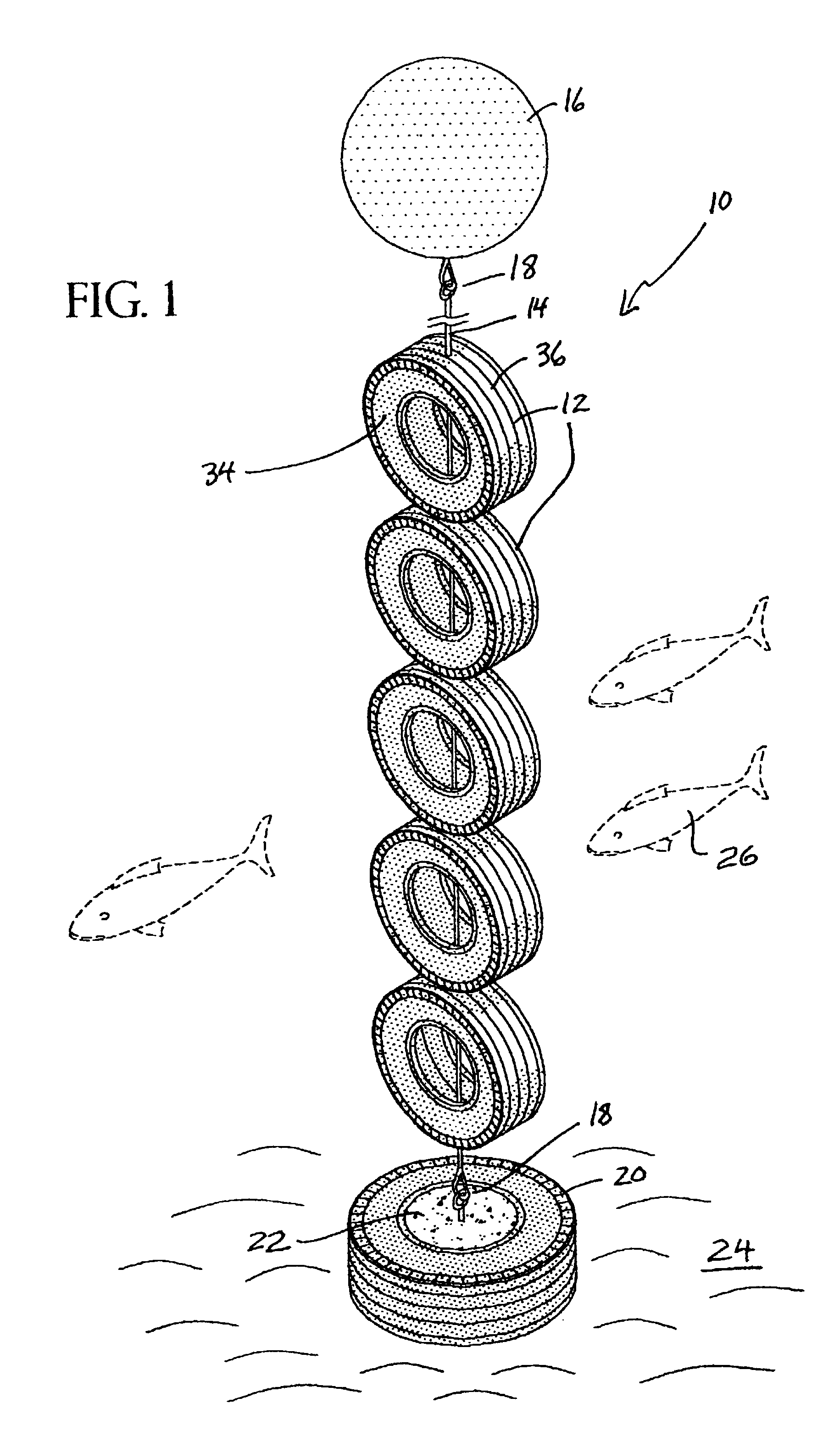
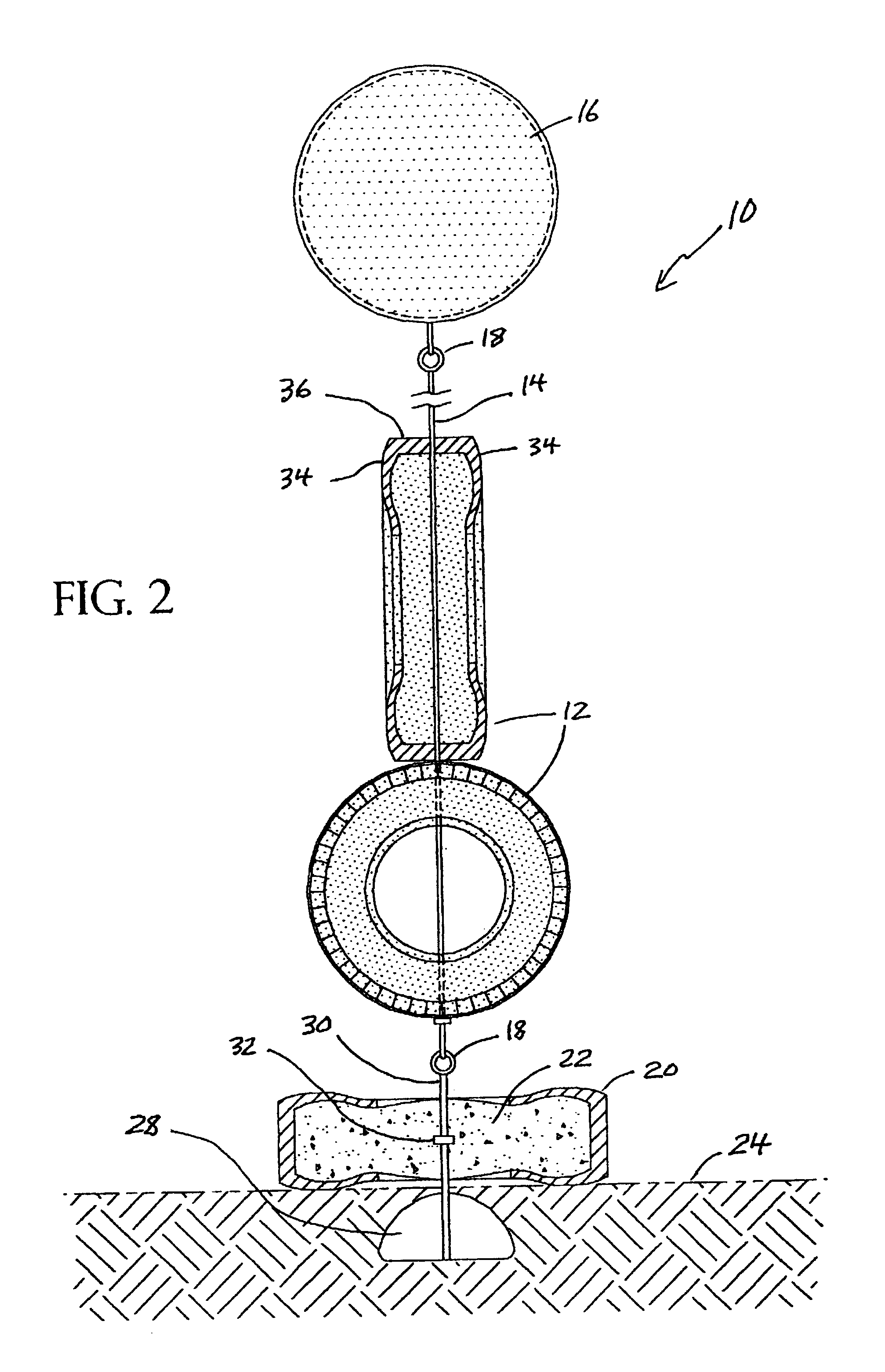
In order that the invention may be more fully understood, it will now be described, by way of example, with reference to the accompanying drawing in which FIGS. 1 through 2 illustrate the present invention wherein an artificial reef system is disclosed.

Turning to FIG. 1, therein is shown a perspective view of the present invention 10 in operative connection. Shown therein are a plurality of tire casings 12 disposed on a cable-like tether or line 14 having connected to the upper end thereof a flotation device 16. At the lower end of the line 14 is another tire casing 20 filled with concrete 22 to prevent the apparatus from shifting in the currents. Many types of heavy objects, e.g., steel or iron, could be used to replace the tire casing 20. Connecting means 18 are shown for connecting the line at its upper end to the flotation device and at its lower end to the concrete filled tire 22. The line of tires is suspended off the floor 24 in an upward standing manner due to the upward pu...


PUM


Abstract

The present invention disclosed an artificial reef system having a plurality of tire casings tethered onto a cable-like line which reef system is supported in an upright position by a flotation device and which artificial reef system is anchored to the bottom of the ocean by another tire casing filled with concrete having an anchoring device disposed on its underside. The cable-like line may be monofilament. The reef system of tire casings is disposed upwardly due to the buoyancy of the flotation device and is free to move with the current in a natural manner to the extent that the cable-like allows. The flotation device may have a rigid wall so that it maintains its surface displacement when subjected to underwater pressure.

Description

1. Field of the InventionThe present invention generally relates to artificial reefs, and, more particularly, is concerned with an artificial reef system composed of vehicle tires.2. Description of the Prior ArtArtificial reef systems have been described in the prior art. However, none of the prior art devices disclose the unique features of the present.In U.S. Pat. No. 6,408,791 B1 dated Jun. 25, 2002, O'Dell disclosed an artificial underwater habitat comprising a structure with a downwardly opening cavity and an upwardly opening cavity including buoyancy means and ballast means. The habitat is preferably constructed in part by used tires. The habitat preferably maintains an upright orientation from the bottom of a body of water to provide an aquatic ecosystem and aquatic food chain at differing depths. The upright orientation of the habitat also minimizes the effect of silting on the habitat. The buoyancy means includes a novel structure for pressurized gas filled containers.In U....

Claims


Application Information

Patent Timeline
Patent Type & Authority Patents(United States)
IPC IPC(8): A01K61/00A01K61/70
CPCA01K61/006A01K61/70Y02A40/81
Inventor HALL, JOHN W.
Owner HALL JOHN W
Why Eureka
Try Eureka