Bioelectrical impedance measuring apparatus

a technology of impedance measurement and bioelectricity, which is applied in the direction of diagnostic recording/measuring, instruments, applications, etc., can solve the problems of inconvenient use of electrodes, inconvenient handling of elongated cables, and inability to accurately measur

Inactive Publication Date: 2004-03-30
TANITA CORP
View PDF13 Cites 101 Cited by
  • Summary
  • Abstract
  • Description
  • Claims
  • Application Information

AI Technical Summary

Benefits of technology

The housing may have indentations formed on its opposite sides, on which indentations the fingers are placed, thereby facilitating the holding of the housing in one hand.
The display may be so arranged that the vertical direction of the display is orthogonally traverse to the direction in which the first pairs of current and voltage electrodes are aligned side by side, thereby facilitating the seeing of the information appearing in its screen.
The grip portion may be so formed to surround the recess, thereby facilitating the holding of the housing in one hand.
The display may be so arranged that the vertical direction of the display is orthogonally traverse to the direction in which the first pairs of current and voltage electrodes are aligned side by side, thereby facilitating the seeing of the information appearing in its screen.

Problems solved by technology

These conventional bioelectrical impedance measuring apparatuses measure bioelectrical impedance by applying two pairs of electrodes to two selected body parts, such as both hands, both feet, or one hand and one foot, and therefore, there must be joints appearing in the current-flowing passage from one body part (or one electrode) to the other body part (or the other electrode), which was found by the inventor to be one major cause for incorrect measurement; during measurement the body sections may be bent or twisted at their joints, thus the object under measurement remains not stationary.
The total distance (for example, two arm lengths plus the trunk width) from one selected body part (one hand) to the other (the other hand) varies significantly with individuals, and therefore, accurate measurements can be hardly expected.
The handling of elongated cables and applying electrodes to selected body parts is inconvenient to use.

Method used


Image

  • Bioelectrical impedance measuring apparatus
  • Bioelectrical impedance measuring apparatus
  • Bioelectrical impedance measuring apparatus

Examples


first embodiment

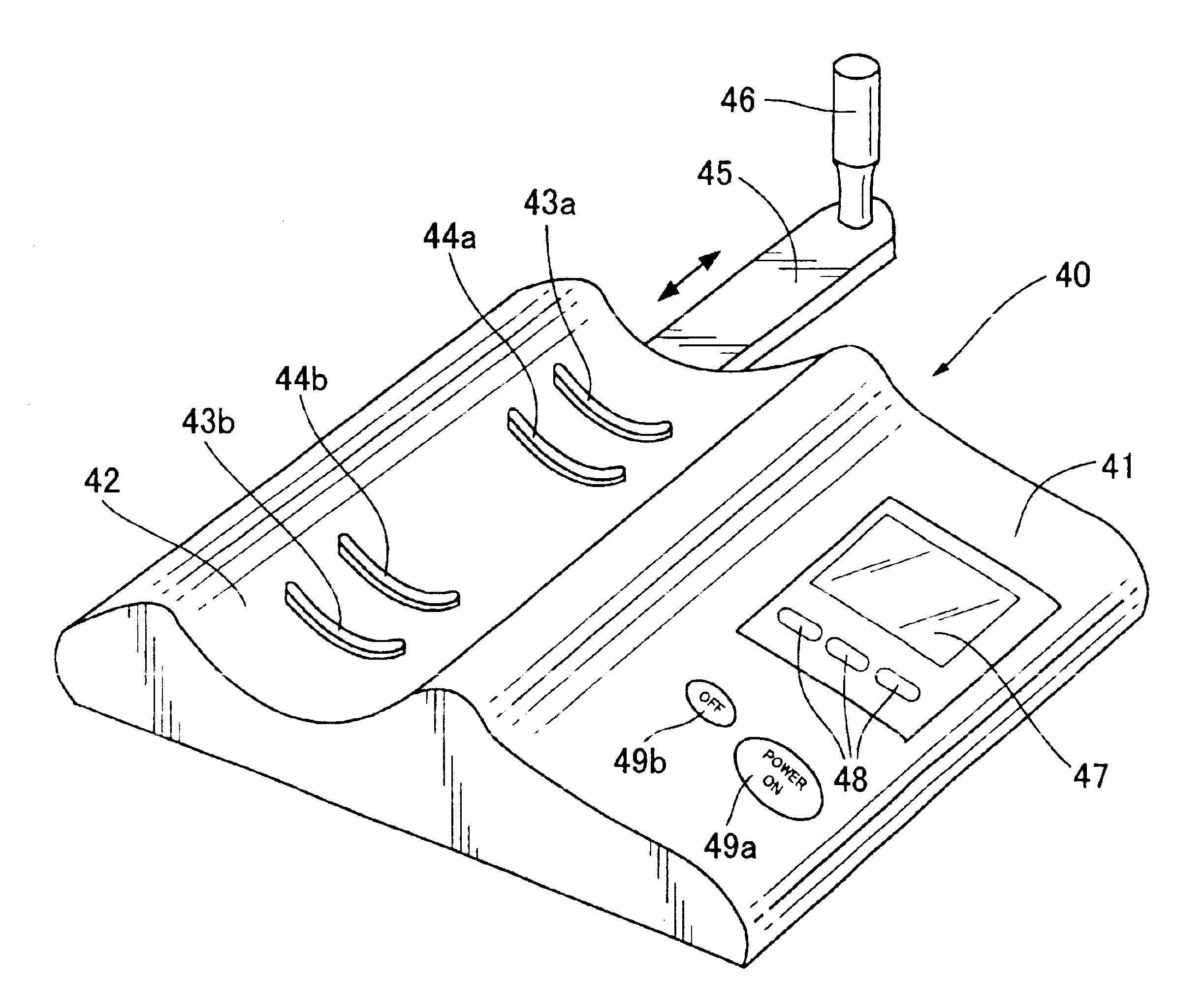
FIG. 4 shows the external appearance of a bioelectrical impedance measuring apparatus according to the first embodiment as viewed from a user, showing how some parts are arranged on the top of the housing 41. The measuring apparatus 40 is designed to measure the bioelectrical impedance appearing between two points selected on the forearm. The housing 41 is of substantially rectangular-planar shape as a whole. The left side of the housing 41 comprises a forearm rest 42 extending from the front to rear side of the housing 41, and the upper surface of the forearm rest 42 looks like a semi-cylindrical trough. A current electrode 43b, a voltage electrode 44b, another voltage electrode 44a and another current electrode 43a are parallel-fixed on the semi-cylindrical surface of the trough in the order named. Each electrode 43a, 44a, 44b or 43b traverses the longitudinal direction of the forearm rest 42, and the electrode is so curved in conformity with the semi-cylindrical surface that they...

second embodiment

FIG. 12 illustrates the external appearance of a bioelectrical impedance measuring apparatus according to the second embodiment as viewed from a user. In the drawing, the same parts as those shown in FIG. 4 are indicated by the same reference numerals. This measuring apparatus 80 is designed to measure the bioelectrical impedance appearing between two points selected on the forearm as in the aforementioned first embodiment. As shown in FIG. 12, an extendable slider 81 having a flat plate for elbow rest 82 is provided on the front side of the housing 41 as a substitute for the forearm slider 45 of the first embodiment. The slider 81 extends in the direction in which the electrodes 43a, 44a, 44b and 43b are arranged side by side. The elbow rest 82 in this particular embodiment takes the role of the stick-like grip 46 in the extendable slider 45 in the first embodiment. The elbow rest 82 comprises elbow-application piece 82a integrally connected to the semicircular end of the flat plat...

third embodiment

FIG. 13 shows the external appearance of a bioelectrical impedance measuring apparatus according to the third embodiment as viewed form a user. In the drawing, the same parts as those of the first embodiment are identified by the same reference numerals (see FIG. 4). This measuring apparatus 90 is also designed to measure the bioelectrical impedance appearing two points selected on the forearm as in the aforementioned first embodiment. The measuring apparatus 90 is a modification of first embodiment of FIG. 4, which additionally includes a cover member 91. The cover member 91 is pivotally fixed to one longitudinal edge of the forearm rest 42, looking like a semi-cylindrical dome in its closed position and extending in the direction in which the electrodes 43a, 44a, 44b and 43b are arranged side by side. Preferably the cover member 91 can be rotated about its pivot axle with counter friction large enough to cause the user to feel some pleasing resistance when he raises his forearm. T...


PUM


Abstract

Disclosed is a impedance measuring apparatus which is easy to use, and which is guaranteed to be free of incorrect measurement caused by some joints appearing in the current flowing passage intervening between two selected body parts and by the indefinite length between two selected body parts. The measuring apparatus of the present invention limits the place of the body under measurement to "one body region", i.e. a selected joint-to-joint body portion or joint-free body portion such as the forearm extending from the wrist to the elbow or the portion extending from the ankle to the knee, and comprises a housing having a contact surface to be applied to one selected body region; a first pair of measurement current supplying electrodes so placed on the contact surface that the one selected body region may be put in contact with the current electrodes; and a first pair of voltage measuring electrodes so placed on the contact surface between the pair of current electrodes that the one selected body region may be put in contact with the voltage electrodes.

Description

1. Field of the InventionThe present invention relates to a bioelectrical impedance measuring apparatus which measures the bioelectrical impedance of a living body, and relates to a bioelectrical impedance measuring apparatus which measures body fat, body water, pulse, blood pressure and such like as well as a bioelectrical impedance of a living body.2. Prior ArtSome examples of conventional bioelectrical impedance measuring apparatus include a cable-connected electrode type of impedance meter 10, a hand-held electrode type of impedance meter 20, and a foot sole-contacting electrode type of impedance meter 30. As shown in FIG. 1, the cable-connected electrode type of impedance meter 10 has a pair of measurement current supplying electrodes 12a, 12b and a pair of voltage measuring electrodes 13a, 13b connected to its cables 11 (hereinafter, a measurement current supplying electrode is called a "current electrode" and a voltage measuring electrode is called a "voltage electrode" in th...

Claims


Application Information

Patent Timeline
Patent Type & Authority Patents(United States)
IPC IPC(8): A61B5/053
CPCA61B5/0537A61B5/4869A61B2560/0468A61B2560/0406
Inventor YAMADA, YASUSHIFUKUDA, YOSHINORITAKEHARA, KATSUMIISHIGOOKA, MAKIMIYOSHI, TSUTOMU
Owner TANITA CORP
Why Eureka
Try Eureka