Spinal-rod connecting apparatus and a connector thereof

a technology of connecting apparatus and rod, which is applied in the field of connecting apparatus and connector thereof, can solve the problems of difficult or inconvenient placement of rod directly at the corresponding bone screw

Inactive Publication Date: 2004-04-06
ROBERT REID INC
View PDF11 Cites 263 Cited by
  • Summary
  • Abstract
  • Description
  • Claims
  • Application Information

AI Technical Summary

Benefits of technology

The through-hole and short rod provided in the connector have an orthogonal relationship, as this arrangement allows the connector to be easily positioned orthogonal to or in parallel to the vertebrae. Further, the spinal-rod connecting apparatus consists of at least two connectors. These connectors may be of the same shape, minimizing the time and costs required for manufacturing the apparatus.
With the multiple connectors, a first connector is set on a rod by inserting the rod into the through-hole therein, the short rod of a second connector is arranged in a rod-attaching portion of a bone screw, and the short rod of the first connector is inserted into the through-hole in the second connector. When the multiple connectors are thus combined, the inclination or the like of the connectors can be corrected by aligning them with the bone screws implanted in the vertebrae, while keeping them parallel with the rods installed in parallel to the vertebrae. That is, the present invention has the advantage of being capable of three-dimensionally modifying the direction in which the bone screws are inserted into the rods when the rods and bone screws are connected.

Problems solved by technology

However, it may be impossible or difficult to place a rod directly at the corresponding bone screw, that is, at the screw-connecting portion, depending on the site at which the rod is attached.
This is impractical.

Method used


Image

  • Spinal-rod connecting apparatus and a connector thereof
  • Spinal-rod connecting apparatus and a connector thereof
  • Spinal-rod connecting apparatus and a connector thereof

Examples


Embodiment Construction

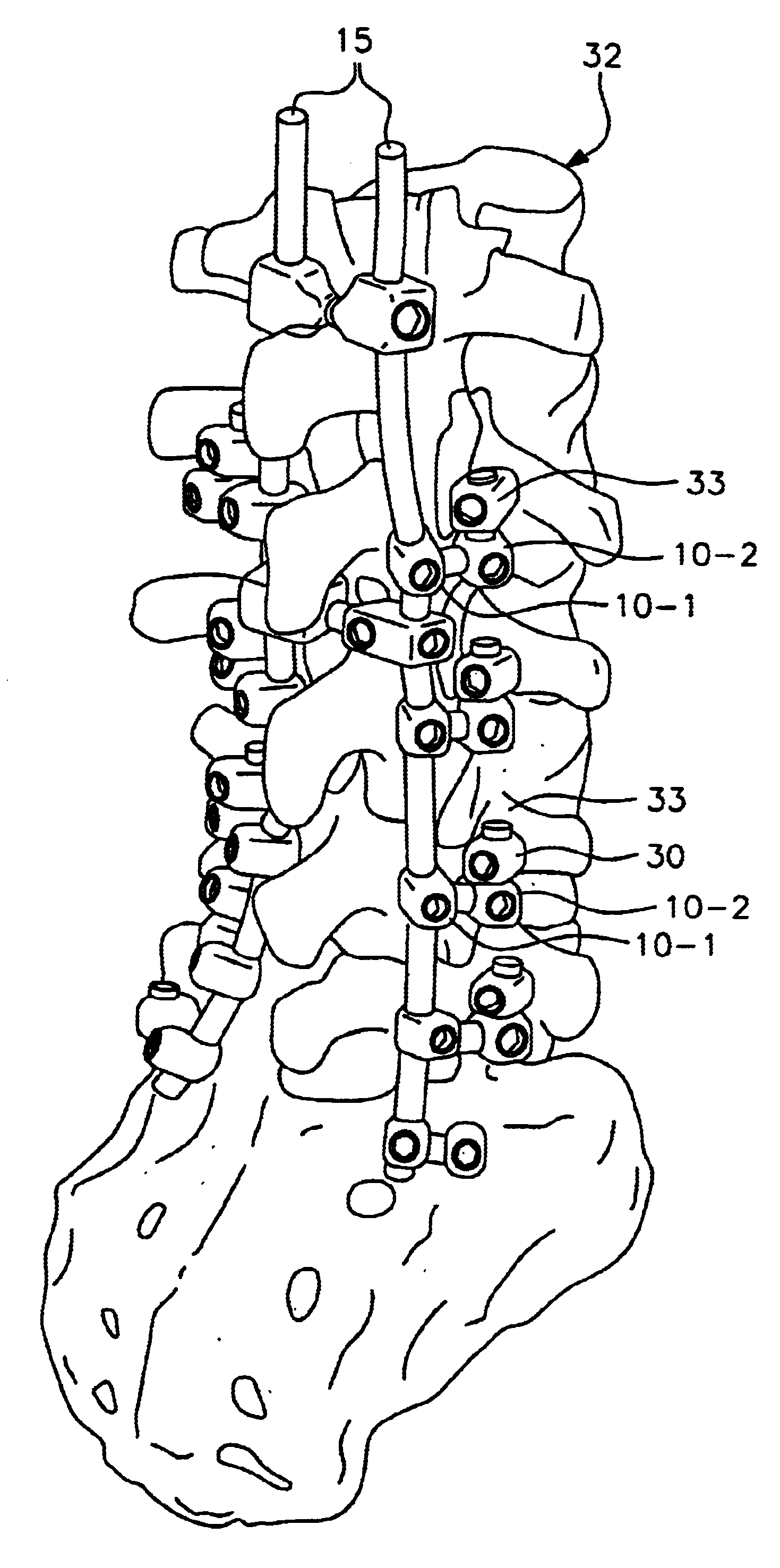
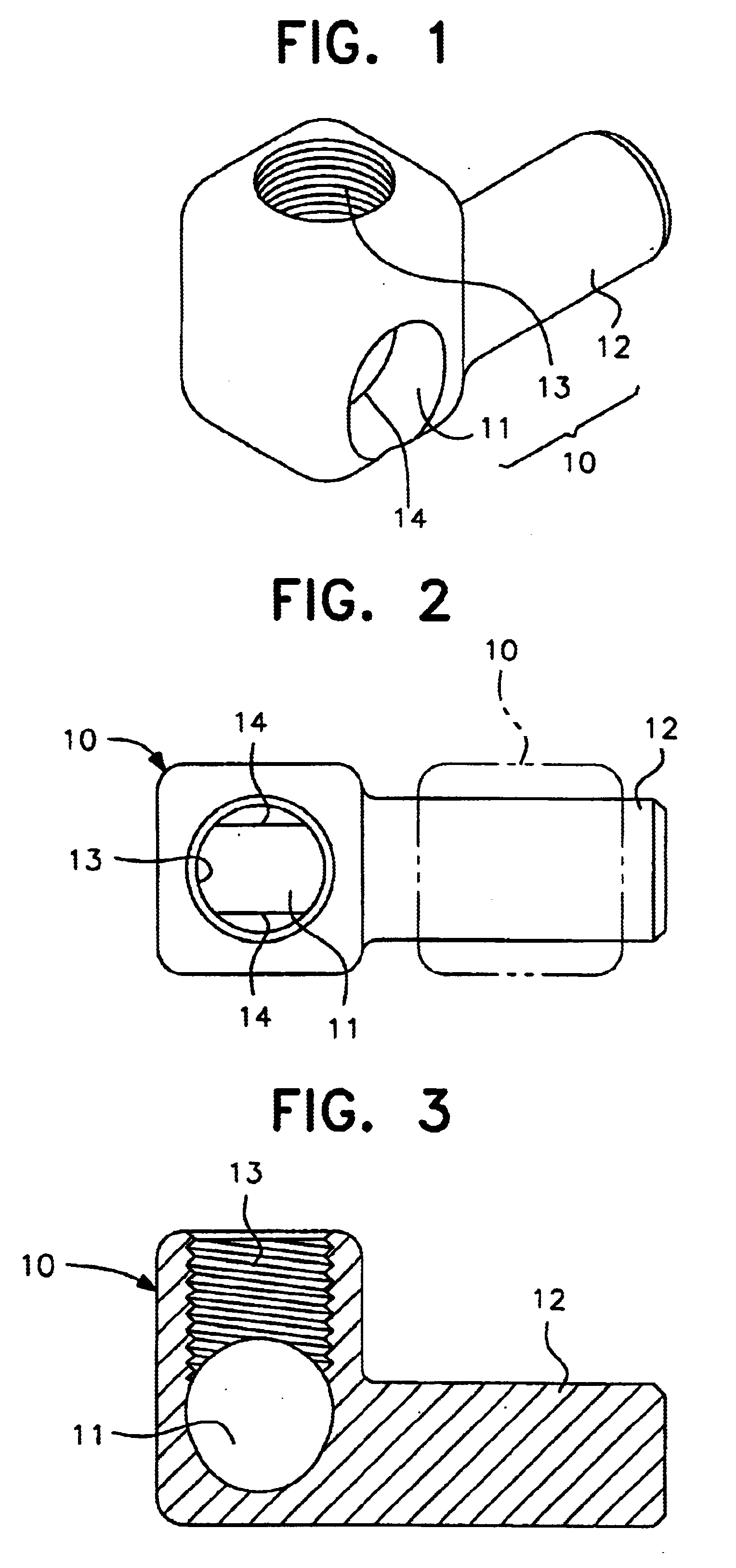
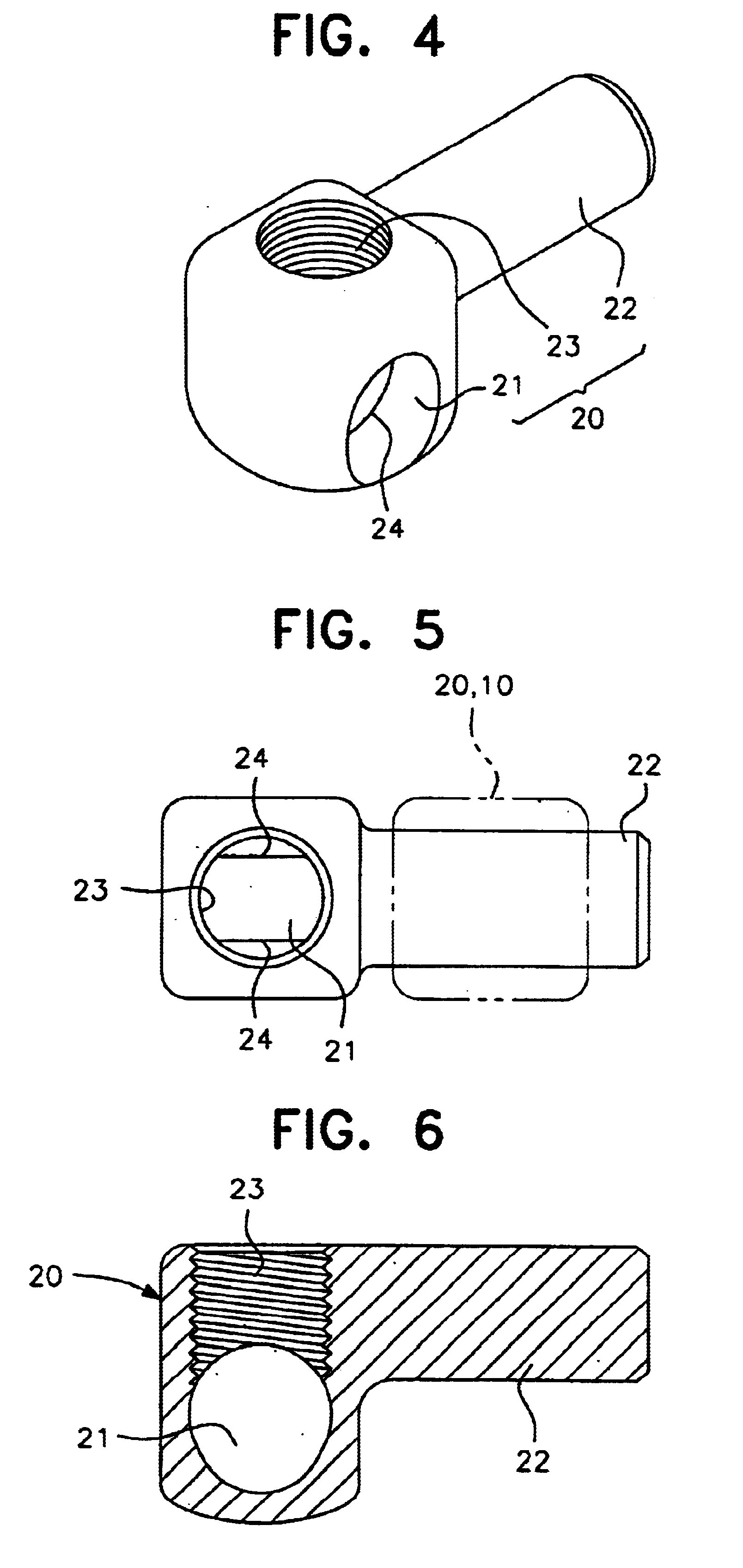
The present invention will be described below in detail with reference to embodiments thereof. FIGS. 1 to 3 show Embodiment 1. This embodiment 1 shows an example of a connector 10. This connector has a through-hole 11 through which a rod 15 can be inserted, a short rod 12 extending orthogonally to the axis of the through-hole 11, and an internal thread portion 13 formed so as to reach the through-hole 11, and in which a screw locks the rod 15 or short rod 12 that is inserted into the through-hole 11.

The connector 10 of Embodiment 1 is an example in which the short rod 12 is provided at a lower position that can be as low as the position of the through-hole 11. The short rod 12 is of a length required to be screwed into the through-hole in another connector 10 (see FIG. 2), and is integrated with the portion having the through-hole 11. Due to its lower position, the through-hole 11 can be connected to a bone-screw member 30 installed in a vertebra 33. The through-hole 11 is designed ...


PUM


Abstract

To avoid requiring physicians to machine a connecting apparatus in the operating room, and to easily and accurately attach and secure rods and bone screws through the appropriate combination of connectors; a feature made possible by multiple connectors, each of which includes a through-hole through which a rod can be inserted, a short rod having the same diameter as the rod, with the short rod being directed in a direction substantially orthogonal to an axial direction of the through-hole and having a length required f or the short rod to be inserted and screwed into the through-hole, and an internal thread portion that allows an external thread member to be screwed therein, with the external thread member locking the rod or short rod inserted into the through-hole; and in which configuration a first connector can be set on the rod by inserting the rod into the through-hole therein, the short rod of a second connector can be arranged in a rod-attaching portion of a bone screw, and the short rod of the first connector can be inserted into the through-hole in the second connector.

Description

The present invention relates to a spinal-rod connecting apparatus for connecting and supporting bone screws implanted in vertebrae and rods installed in parallel to the vertebrae.DESCRIPTION OF THE PRIOR ARTAn operation is performed that holds the spine in a desirable position by implanting a required number of bone screws in vertebrae and connecting them to rods. Each of the bone screws has a connecting portion through which the rod is inserted and screwed. Such connecting portions are roughly divided into those shaped like holes formed in what are referred to as "closed screws," into which rods are inserted in an axial direction, and those shaped like grooves formed in what are referred to as "open screws" for receiving rods therein. However, it may be impossible or difficult to place a rod directly at the corresponding bone screw, that is, at the screw-connecting portion, depending on the site at which the rod is attached. In such cases, it is contemplated that an auxiliary part...

Claims


Application Information

Patent Timeline
Patent Type & Authority Patents(United States)
IPC IPC(8): A61B17/70A61B17/86A61B17/68A61B17/58
CPCA61B17/7035A61B17/7041A61B17/7049A61B17/8605
Inventor SHITOTO, HIDEO
Owner ROBERT REID INC
Why Eureka
Try Eureka