Anchor fluke

a technology of anchor fluke and spherical spherical spherical, which is applied in the direction of anchors, waterborne vessels, vessel parts, etc., can solve the problems of increasing the production cost of anchors in question, and affecting the stability of anchorag

Inactive Publication Date: 2004-04-13
STEVLOS
View PDF11 Cites 0 Cited by
  • Summary
  • Abstract
  • Description
  • Claims
  • Application Information

AI Technical Summary

Problems solved by technology

After having been lowered, the position taken up by the anchor fluke on the ground will not always be optimal for penetration into the anchorage ground.
This will cause production costs of the anchors in question to rise.
However, it is possibly more important that the protruding parts form objects that are easily damaged or may easily cause damage to other objects and have an unfavourable influence on penetration.

Method used


Image

  • Anchor fluke
  • Anchor fluke
  • Anchor fluke

Examples


Embodiment Construction

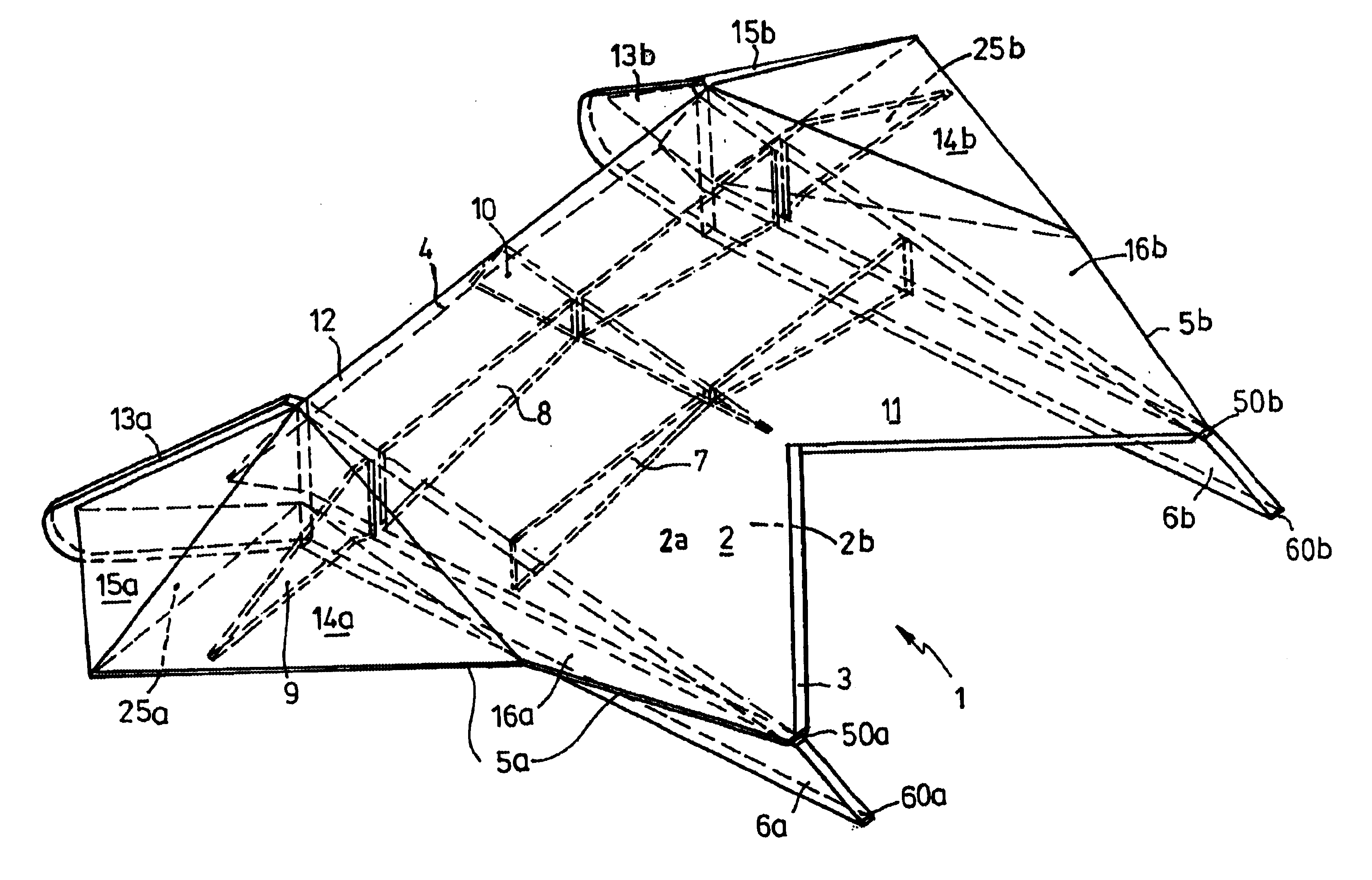
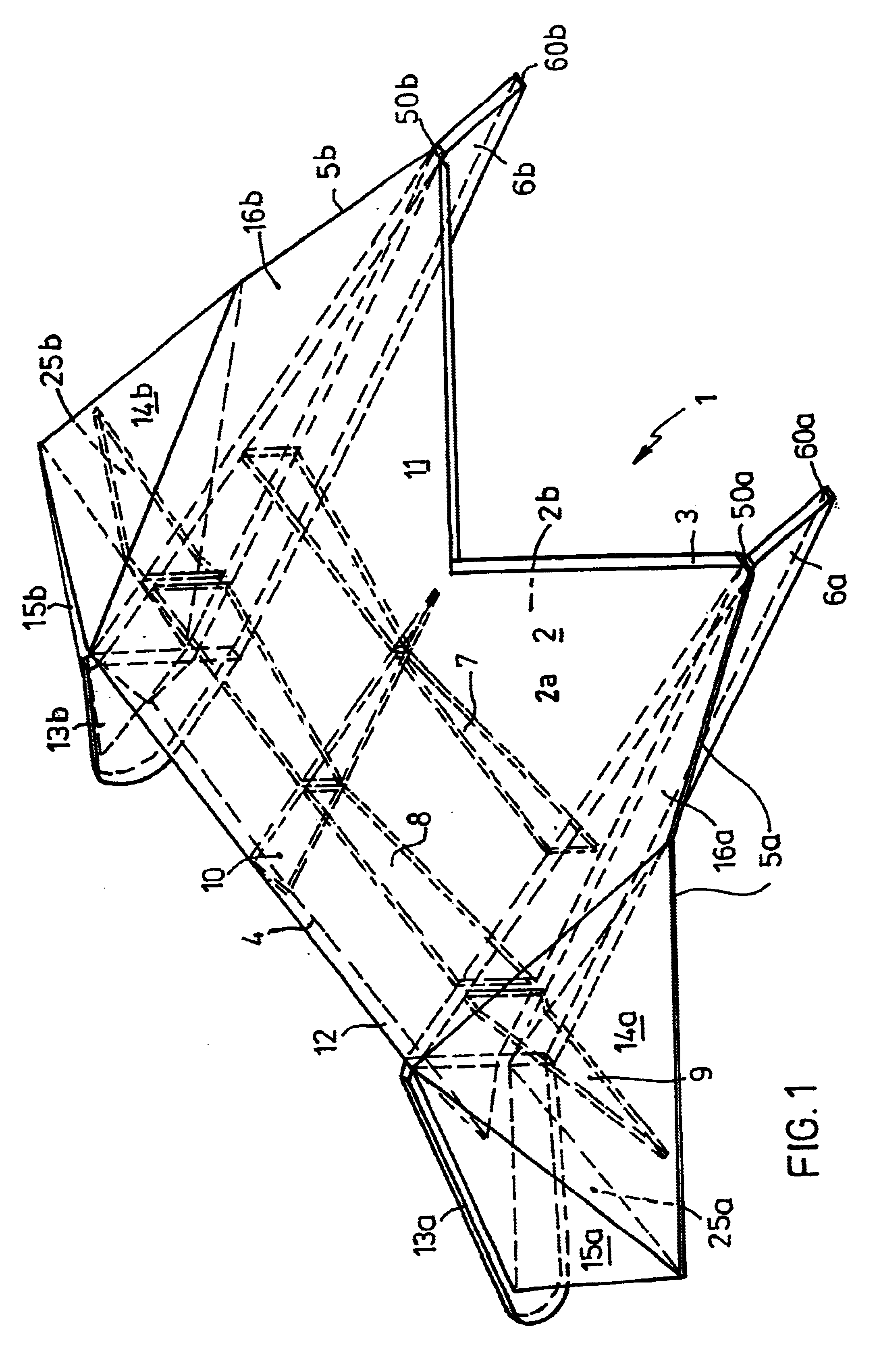
The anchor fluke of FIG. 1 is a so-called hollow fluke that is bounded at the upper side and lower side by upper plate assembly 2a and lower plate assembly 2b, respectively. Cross girders 7 and 8 and longitudinal girders 6a and 6b and 10 are located between these two plate assemblies 2a and 2b . Here, the longitudinal girders 6a and 6b project from the lower side, but that is not absolutely necessary, and likewise, at the front side with penetration points 60a and 60b and at the rear side by means of trailing plates 13a and 13b, which are turned at an angle, diverge with respect to one another and project from the lower side of the fluke.

In order to provide strength at the areas of the anchor fluke 1 lying outside the longitudinal girders 6a and 6b, the cross girder 8 is prolongated in substantially triangular end cross girders 9a, 9b, which extend obliquely downwards to the side.

At its front side or penetration side, the anchor fluke 1 is bounded by a V-shaped front edge 3, which e...


PUM


Abstract

Anchor fluke (1) having a hollow plate-shaped body adapted for attachment to a shank and/or anchor lines, with a longitudinal axis and a front penetration edge (3) and a rear trailing edge (4), which are located at a distance from one another in the direction of the longitudinal axis, wherein the fluke has a plane of symmetry that contains the longitudinal axis and is substantially perpendicular to the plate-shaped body. The hollow plate-shaped body has an upper surface (2a) with a centre of gravity and a lower surface (2b) which surfaces are bounded by the penetration edge, the trailing edge and lateral edges (5a, 5b) and wherein the body, at the lower surface, substantially between the edges, is provided with surfaces for counteracting a rolling movement about the longitudinal axis during penetration of the anchor fluke in an anchorage ground, and with vertical trailing edges (13a, 13b) for counteracting a yawing movement about an axis that is perpendicular to the longitudinal axis and is located in the plane of symmetry during the penetration in an anchorage ground.

Description

The invention relates to an anchor fluke. An anchor fluke forms that part of an anchor that has to produce the holding (counter) force necessary for the anchorage of an object. The anchor fluke is provided with means for attachment at the lower end of an anchor shank, which may have a rigid (plates) or flexible (cables, chains) construction and, at its upper end, is provided with means for attachment to the lower end of a penetration or anchor line, with which the anchor fluke can be drawn into the anchorage ground and be connected to the object that has to be anchored.BACKGROUND AND PRIOR ARTAfter having been lowered, the position taken up by the anchor fluke on the ground will not always be optimal for penetration into the anchorage ground. This may be the result of an asymmetric landing of the anchor fluke or an asymmetrically shaped basis (irregularities). Then, when the penetration line is hauled in, the anchor fluke will penetrate into the ground in an oblique manner, as viewe...

Claims


Application Information

Patent Timeline
Patent Type & Authority Patents(United States)
IPC IPC(8): B63B21/30B63B21/40B63B21/24
CPCB63B21/30B63B21/40B63B2021/262
Inventor DEGENKAMP, GIJSBERTUS
Owner STEVLOS
Why Eureka
Try Eureka