Ink-jet printing apparatus and ink-jet printing method

a technology of inkjet printing and printing method, which is applied in the direction of printing, other printing apparatus, etc., can solve the problems of unfavorable use, uneven ejection openings, and uneven printing image density, and achieve the effect of reducing color bleeding

Inactive Publication Date: 2004-04-13
CANON KK
View PDF10 Cites 12 Cited by
  • Summary
  • Abstract
  • Description
  • Claims
  • Application Information

AI Technical Summary

Benefits of technology

is to provide an ink-jet printing method and an ink-jet printing apparatus for printing a high-quality image with reduced bleeding in colors that may appear in multi-pass printing.
According to the above structure, when so-called multi-pass printing is performed, for the first and the second ejection opening rows, the positions of the ejection openings located at ends of the respective first and the second ejection opening rows on a paper feeding side or a paper discharging side in connection with feeding of a printing medium are apart from each other at a distance of (m+a).times.L (a: positive integer) in a discharging or feeding direction for conveying a printing medium. Or between scanning for completing printing on a first image and first scanning for printing a second image, scanning with performing no printing is executed for an area on which the first image has been printed. Hence, printing an image by the first ejection opening row and printing an image, which is adjacent to the image by the first ejection opening row, by the second ejection opening row are performed while at least a single scanning is executed therebetween. Therefore, it is possible to provide time for fixing ink by the first ejection opening row onto the printing medium.

Problems solved by technology

Particularly, it has been known that regarding the uniform density, due to slight unevenness of ejection openings on manufacturing that occurs in a process of manufacturing a printing head, an amount of ejected ink and an ejecting direction may vary among the ejection openings, resulting in uneven density of the printed image.
However, as described above, ejection openings actually have unevenness to some extent.
However, in the case of using the multi-pass printing mentioned before, when it is intended that the bleed at a boundary (hereinafter, also referred to as "bleeding in colors") is reduced between the black image and the color image, the method of Japanese Patent Laid-Open No. 06-135014 cannot be used as it is.
Therefore, even when the method is used as it is, scanning for obtaining fixing time cannot be provided.

Method used


Image

  • Ink-jet printing apparatus and ink-jet printing method
  • Ink-jet printing apparatus and ink-jet printing method
  • Ink-jet printing apparatus and ink-jet printing method

Examples


first embodiment

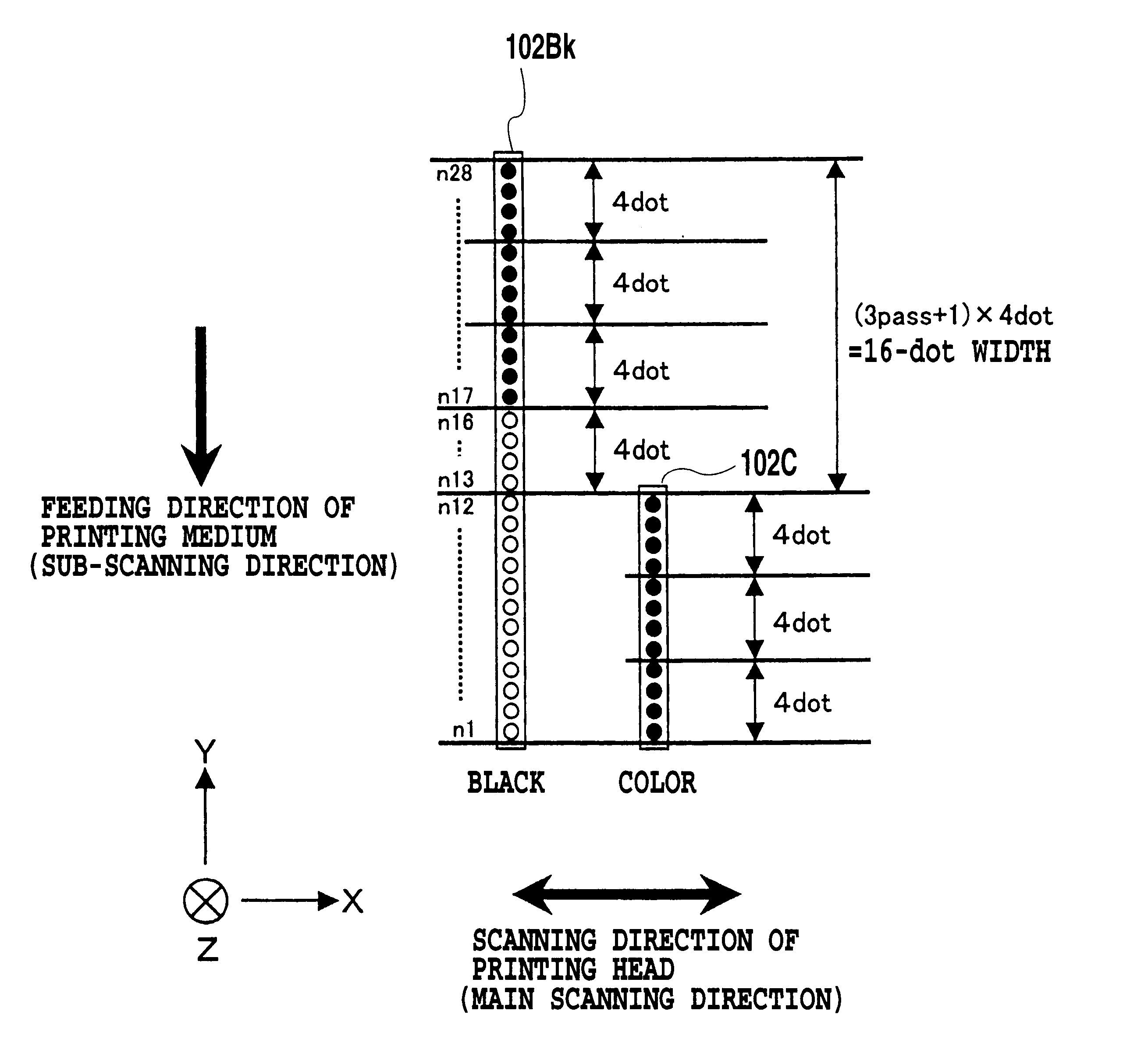
FIG. 8 is a diagram showing printing heads according to the first embodiment of the present invention. A first printing head (hereinafter, also referred to as a black head) 102Bk of the present embodiment for ejecting black ink has n=28 ejection openings arranged in a sub-scanning direction, which is a direction of feeding the printing medium, at a density of N=600 per inch (600 dpi). As compared with this, printing heads 102C (hereinafter, referred to as color heads and referred to as a single printing head 102C representing the heads) respectively ejecting ink of cyan (C), magenta (M) and yellow (Y) have n=12 ejection openings arranged similarly in the sub-scanning direction at a density of N=600 per inch (600 dpi). And then, the color head 102C is installed on the printing apparatus such that 12 ejection openings n1 to n12 are disposed on the same positions as 12 ejection openings n1 to n12 of the black head 102Bk in a sub-scanning direction. Therefore, other ejection openings n1...

second embodiment

FIG. 15 is a diagram showing a configuration of ejection opening rows of printing heads for black ink and color ink according to a second embodiment of the present invention.

A printing head 102Bk shown in FIG. 15 for ejecting black ink arranges n=24 ejection openings at a density of N=600 per inch (600 dpi). In a full-color printing mode, only six ejection openings n19 to n24 are used among them. As compared with this, a printing head 102C for ejecting color ink arranges n=12 ejection openings at a density of N=600 per inch (600 dpi). In a full-colormode, 12 ejection openings n1 to n12 are all used. Further, a positional relation between the respective ejection openings in the printing heads is that respective ejection openings having the same ejection opening numbers coincide with each other in a sub-scanning direction, and in a main scanning direction, the respective ejection openings of the printing heads are apart from each other at a predetermined interval.

Additionally, as desc...

third embodiment

FIG. 19 is a diagram showing the arrangement of ejection openings on printing heads for ejecting black ink and color ink according to a third embodiment of the present invention.

A black head 102Bk of the present embodiment has n=24 ejection openings arranged with a density of N=600 per inch (600 dpi). Ejection openings used for a full-color mode of the present embodiment are six ejection openings n1 to n6. Further, a color head 102C has n=12 ejection openings arranged with a density of N=600 per inch (600 dpi). In a full-color mode, twelve ejection openings n1 to n12 are all used. And then, a positional relationship between the ejection openings of the respective printing heads is that in a sub-scanning direction, the ejection openings n13 to n24 of the black head 102Bk are arranged on the same positions as the ejection openings n1 to n12 of the color head 102C. On the other hand, in a main scanning direction, the ejection openings of the respective printing heads are disposed at a ...


PUM


Abstract

A high-quality image is printed with reduced bleeding in colors that may appear at a boundary between a black image and a color image. A head for ejecting black ink and a head for ejecting color ink perform three times of scanning while feeding is carried out therebetween for moving the printing medium by four pitches of ejection openings arranged on the heads, different ejection openings are caused to correspond to a scanning area, which corresponds to the four pitches, and multi-pass printing is performed to complete printing on the area. The black head completes printing of the black image, and then, the color head completes printing of the color image adjacent to the black image. The arrangement of ejection openings is determined so that between last scanning for completing printing of the black image and the first scanning for printing of the color image, scanning with no performing printing exists.

Description

This application is based on Patent Application No. 2000-366291 filed Nov. 30, 2000 in Japan, the content of which is incorporated hereinto by reference.1. Field of the InventionThe present invention relates to an ink-jet printing method and an ink-jet printing apparatus and specifically to a configuration for reducing bleeding at a boundary between black and color image areas printed when black ink and other kinds of color ink are used for printing.2. Description of the Related ArtA printing apparatus having a function of a printer, a copy machine, a facsimile or the like, or a printing apparatus used as an output device of information processed in a composite electronic device including a computer and a word processor, a work station and so on, is structured so that images (including characters and so on) are printed on a printing medium such as a printing sheet and a plastic thin plate based on image information (including character information). Such a printing apparatus is, by ...

Claims


Application Information

Patent Timeline
Patent Type & Authority Patents(United States)
IPC IPC(8): B41J2/21B41J2/01
CPCB41J2/2132
Inventor KANDA, HIDEHIKOMORIYAMA, JIRONAKAGAWA, YOSHINORI
Owner CANON KK
Why Eureka
Try Eureka