ROV installed suction piles

Inactive Publication Date: 2004-04-13
SHELL OIL CO
View PDF76 Cites 61 Cited by
  • Summary
  • Abstract
  • Description
  • Claims
  • Application Information

AI Technical Summary

Benefits of technology

One aspect of the present invention is a method for deploying a suction pile anchor in which flood valves are opened on the top of a suction pile and the suction pile anchor is off loaded from the anchor boat and lowered it to the sea floor. The suction pile anchor is set down and the rate of feed is adjusted to match the rate of self-penetration. An ROV with pump capability closes the flood valves on the top of t

Problems solved by technology

Installing such foundation elements for secure anchorage is time consuming and requires considerable offshore equipment.
Another problem arising in deepwater is that the spread of these mooring lines can be substantial and anchor structures are widely placed over a leasehold or even into adjacent lease blocks and the mooring arrays of adjacent blocks can overlap.
Further, the sequential steps in development such as explor

Method used


Image

  • ROV installed suction piles
  • ROV installed suction piles
  • ROV installed suction piles

Examples


Embodiment Construction

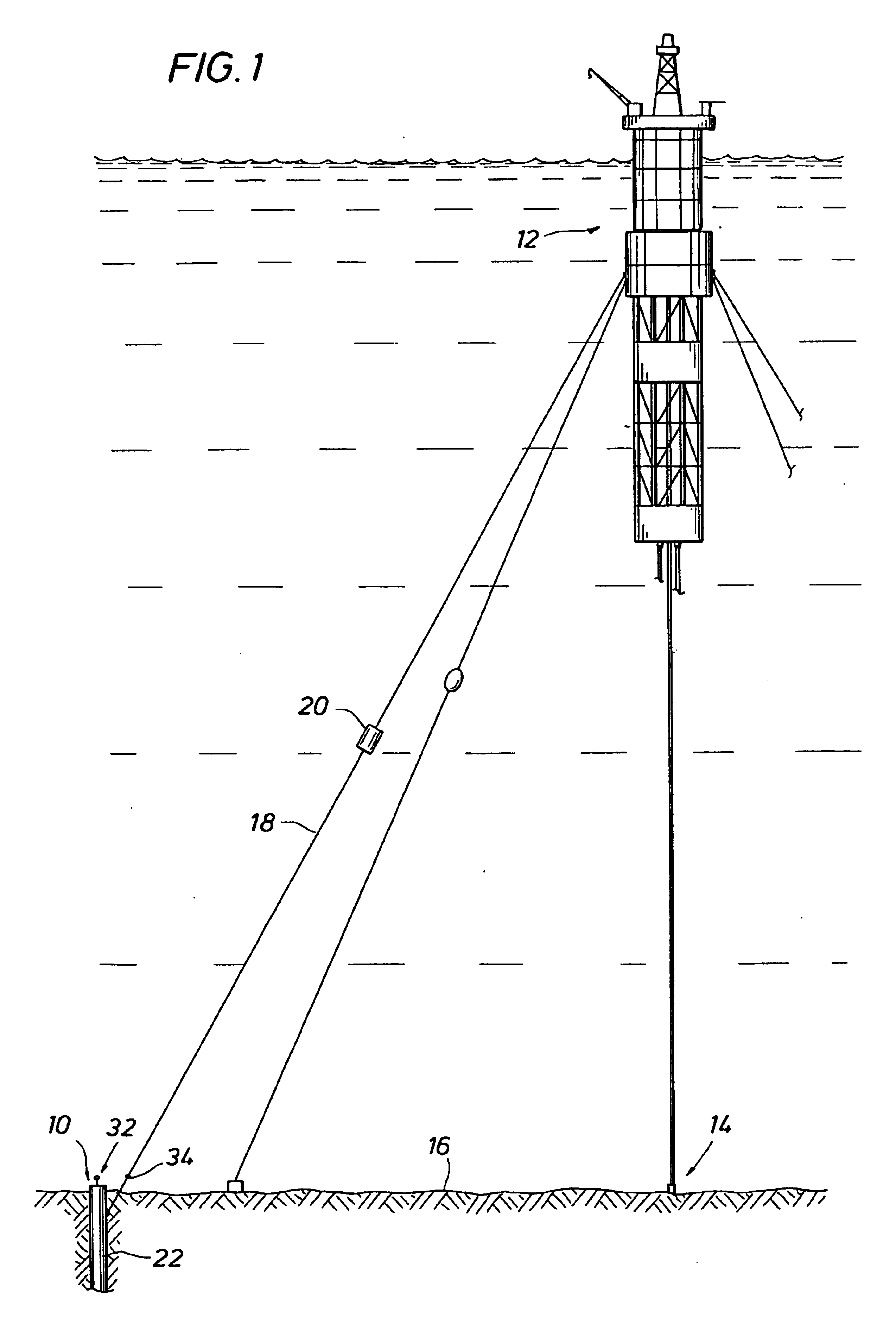
FIG. 1 illustrates one application of the present invention. Here the suction pile anchors 10 secure a truss spar configuration mobile offshore drilling unit ("MODU") 12 in position over well site 14 at ocean floor 16. Each suction pile anchor is securely set within the ocean floor and is connected to MODU 12 through mooring or load lines 18. The use of taut line moorings may reduce the mooring spread. Further, buoys 20 may be included into the mooring lines.

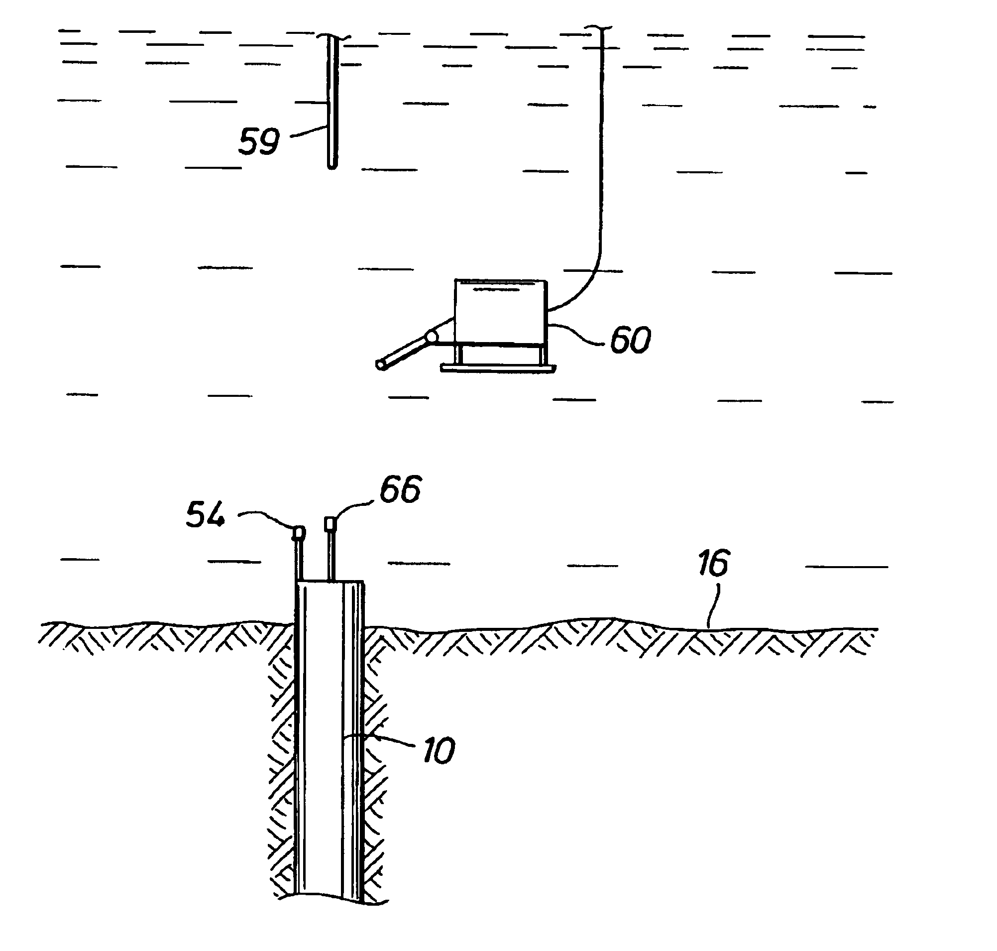
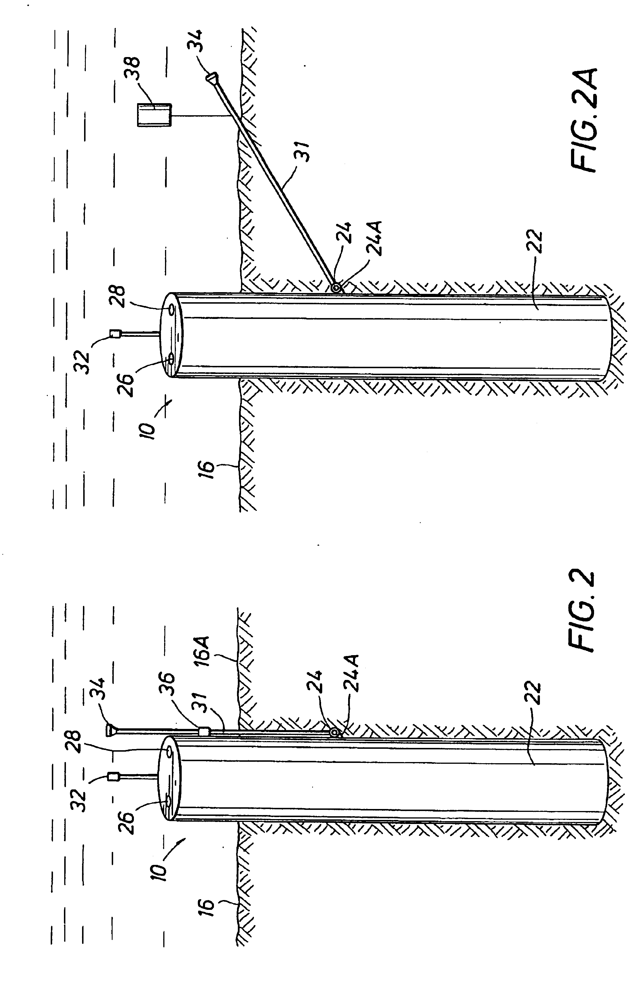
FIG. 2 illustrates a suction pile anchor 10 installed in ocean floor 16. The suction pile anchor has a suction pile 22, here in the form of a closed top cylinder. A first load connection 24, here provided by load pad-eyes 24A, is provided on the side of the suction pile, positioned to be away from the ends of the suction pile and well below the mud line on deployment. Under load conditions with this configuration, the load will be resisted most efficiently against the mud.

Flooding ports or valves 26 and pump or pressure port or ...


PUM


Abstract

A method is disclosed for deploying a suction pile anchor in which flood valves are opened on the top of a suction pile and the suction pile anchor is off loaded from the anchor boat and lowered it to the sea floor. The suction pile anchor is set down and the rate of feed is adjusted to match the rate of self-penetration. An ROV with pump capability closes the flood valves on the top of the suction pile and attaches to the pumping port of the suction pile. The pump of the ROV operates to draw down the suction pile to full depth and brings the first load line connection and the attached first end of the load line well below the mudline while the second load connection at the second end of the load line is supported above the mudline. The ROV disconnects from the pump port and connects a mooring line to second the load connection. Another aspect of the present invention is a suction pile system having a suction pile with an ROV compatible pressure port and a flood valve at the top. A load support system includes a first load connection on the side of the suction pile with a load line connected to the first load connection. A second, ROV accessible load connection is provided at the distal end of the load line.

Description

The present invention relates to a method and system for securing offshore vessels and structures and, more particularly, to anchoring offshore drilling and / or production vessels in relation to the ocean floor.Surface facilities must be maintained in position over a well site for offshore drilling operations and often for production operations. This often requires the deployment of an array of mooring lines, each anchored to the seabed with a pile foundation or the like. Installing such foundation elements for secure anchorage is time consuming and requires considerable offshore equipment.Another problem arising in deepwater is that the spread of these mooring lines can be substantial and anchor structures are widely placed over a leasehold or even into adjacent lease blocks and the mooring arrays of adjacent blocks can overlap. Further, the sequential steps in development such as exploration wells, test wells, satellite subsea wells, etc. can each leave foundation elements until th...

Claims


Application Information

Patent Timeline
IPC IPC(8): B63B21/27B63B21/22B63B21/00B63B21/24
CPCB63B21/22B63B21/27B63B2021/007B63B2021/505E02D2250/0053
Inventor VON EBERSTEIN, WILLIAM HENRY
Owner SHELL OIL CO
Why Eureka
Try Eureka