Tree step tool and method

a tree step and tool technology, applied in the field of tree step tools and methods, can solve the problems of increasing the possibility of the tool becoming useless, inconvenient to carry, and bulky conventional tools, and achieve the effect of easy setting and removing portable steps, and easy unthreading of tree steps

Inactive Publication Date: 2004-05-04
APPLE GREGORY L
View PDF10 Cites 29 Cited by
  • Summary
  • Abstract
  • Description
  • Claims
  • Application Information

AI Technical Summary

Benefits of technology

The aforesaid and other objectives are realized by providing a tool for easily setting and removing portable steps from a support such as a tree trunk. The tool includes a somewhat pear-shaped handle which is in axial alignment with a U-shaped channel member. An impact rod is positioned inside the U-shaped channel member and extends toward the distal end thereof. The pear-shaped handle is affixed to the impact rod. The method of use of the tool demonstrates placing a tree step having a pivotal, pointed and threaded lug in the U-shaped channel member whereby the blunt or rear end of the threaded lug contacts the impact rod near the axle pin. The threaded lug is then positioned against a tree trunk while inside the tool whereupon the tool handle can be manually struck to drive the pointed threaded lug slightly, into the tree. Next, the tree step and tool can be turned in a clockwise direction to rotate the threaded lug into the tree trunk for securement. Once the tree step is then properly set, the tool is removed and the tree step can then pivot downwardly at the axle pin to its normal configuration against the tree and be used in climbing. The tools handle which may be formed of a polymeric material has a pear shape and is in axial alignment with the longitudinal axis of the U-shaped member. Thus, with the tree step inserted in the tool, the tool handle can be struck to start the threaded lug into the tree trunk. To remove the tree step, the tool is placed on the tree step in a different manner, with the step tread in the tool U-shaped channel member and is used to rotate the step in a counter clockwise direction, thus easily unthreading the tree step from the tree trunk or other support.

Problems solved by technology

Conventional tools are generally bulky and inconvenient to carry in that they have a handle at an approximate 90 degree angle to the tool body.
Also, certain of the prior art tools require assembly and the use of two or more tool components increases the possibility of the tool becoming useless, should one of the components be lost.

Method used


Image

  • Tree step tool and method
  • Tree step tool and method
  • Tree step tool and method

Examples


Embodiment Construction

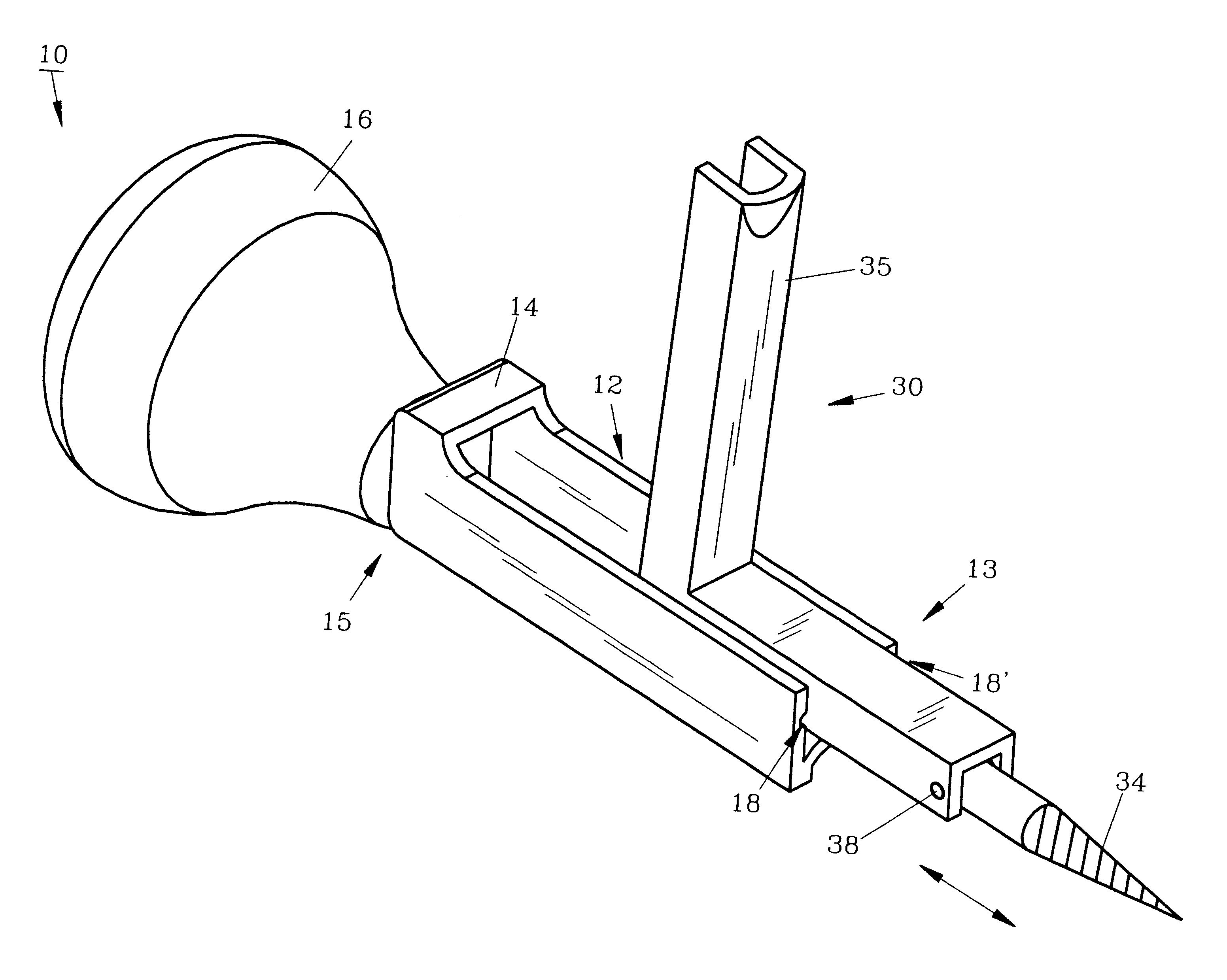
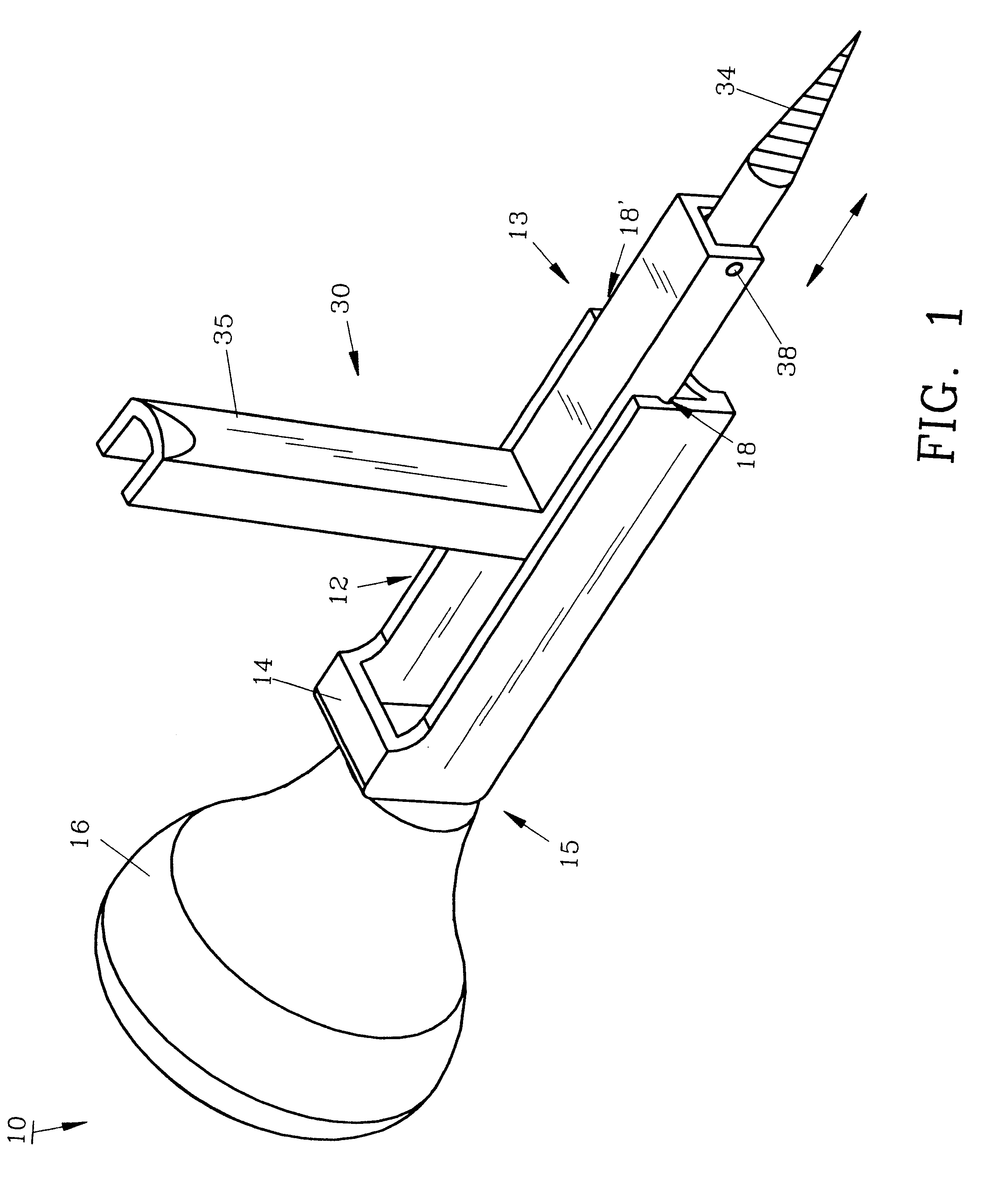
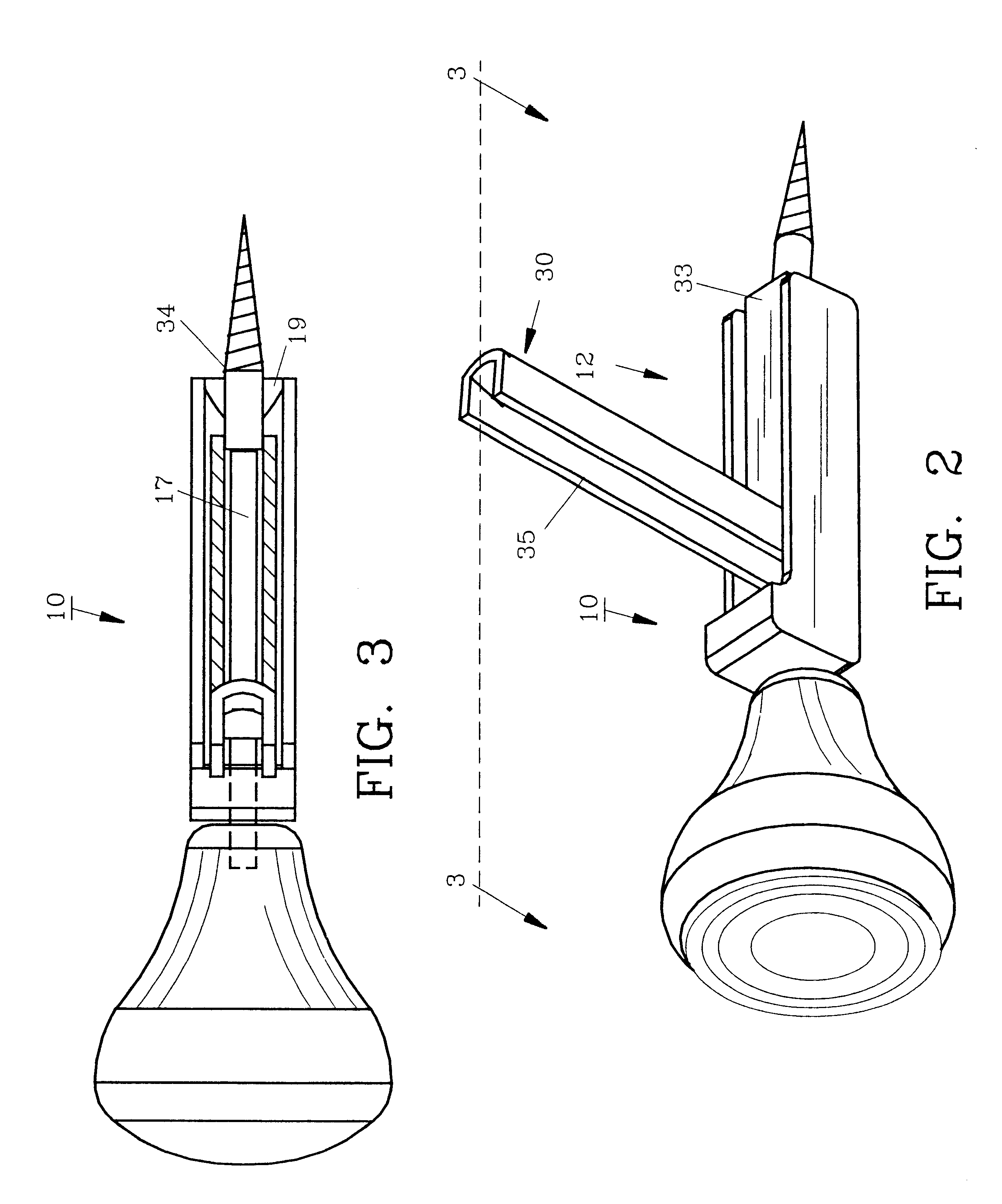
For a better understanding of the invention and its operation, turning now to the drawings, FIG. 1 demonstrates preferred tree step tool 10 with a standard L-shaped portable tree step 30 partially positioned in U-shaped channel member 12. U-shaped channel member 12 includes an open distal end 13 and a channel hood 14 at proximal end 15. Affixed to U-shaped channel member 12 is a rotatable pear-shaped handle 16 which is joined to and axially aligned with impact rod 17, as shown in FIG. 3. Pin groove 18 extends about one-half the length of U-shaped channel member 12 to accommodate axle pin 38. A second pin groove 18' (not shown) is on the opposite side of U-shaped channel member 12. The axial alignment allows compact storage and carrying of tool 10 in the pockets of the pants or a jacket due to its slight bulk.

Pear-shaped handle 16 as seen in FIGS. 9, 10 and 11 may be formed of a hardwood, polymeric material or the like, to withstand manual blows during usage. Impact rod 17 is formed ...


PUM


Abstract

Mounting for portable, removable steps on tree trunks or other supports and particularly pertaining to a tool and method for easy, conveniently mounting conventional tree steps. The tool as described includes a handle axially aligned with a channel member containing an impact rod. A tree step is placed within the channel member and can then be rotated in a clockwise direction into the tree trunk or in a counter clockwise direction to remove the mounted step from the tree trunk.

Description

The invention herein pertains to a tool for mounting steps on a tree trunk or other support and particularly pertains to a tool which can be readily used to attach and remove conventional, portable L-shaped steps.DESCRIPTION OF THE PRIOR ART AND OBJECTIVES OF THE INVENTIONVarious designs for portable tree steps have been available for many years and used by hunters and others for climbing trees. U.S. Pat. No. 4,697,669 demonstrates a typical step having a threaded pivotal member for attachment purposes. To help attach such portable steps, a variety of tools or wrenches have been devised in the past as shown in U.S. Pat. Nos. 5,899,124, 5,743,353 and 5,624,007. Conventional tools are generally bulky and inconvenient to carry in that they have a handle at an approximate 90 degree angle to the tool body. Also, certain of the prior art tools require assembly and the use of two or more tool components increases the possibility of the tool becoming useless, should one of the components be...

Claims


Application Information

Patent Timeline
Patent Type & Authority Patents(United States)
IPC IPC(8): A63B27/00A63B29/04
CPCA63B27/00
Inventor APPLE, GREGORY L.
Owner APPLE GREGORY L
Why Eureka
Try Eureka