
Motorized climbing hunting stand

a hunting stand and motorized technology, applied in the field of hunting stands, can solve the problems of difficult and time-consuming erecting of permanent stands, inability to move between hunting locations without significant time-consuming effort, and the seat cannot be easily moved vertically, etc., to achieve convenient disassembly and transportation, simple operation, and easy deployment

Inactive Publication Date: 2008-11-06
MOTES OUTDOOR EQUIP
View PDF13 Cites 29 Cited by
  • Summary
  • Abstract
  • Description
  • Claims
  • Application Information

AI Technical Summary

Benefits of technology

[0018]This invention provides a motorized, elevating device that safely and reliably elevates a user to a desired vertical elevation along an elongated, cylindrical object such as a pole. Preferably the device functions as a deer stand, and it is deployed within the woods against a selected tree. My invention provides a power means to elevate the hunter to a desired position vertically above ground.
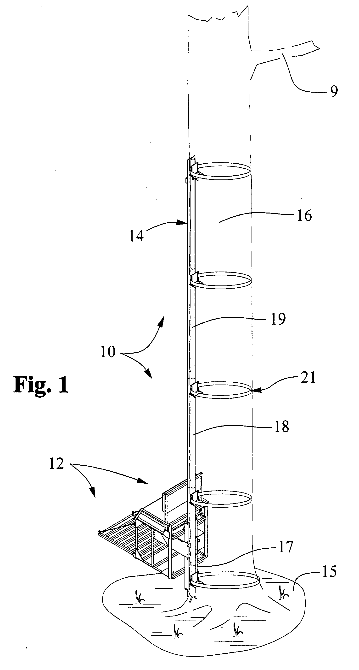
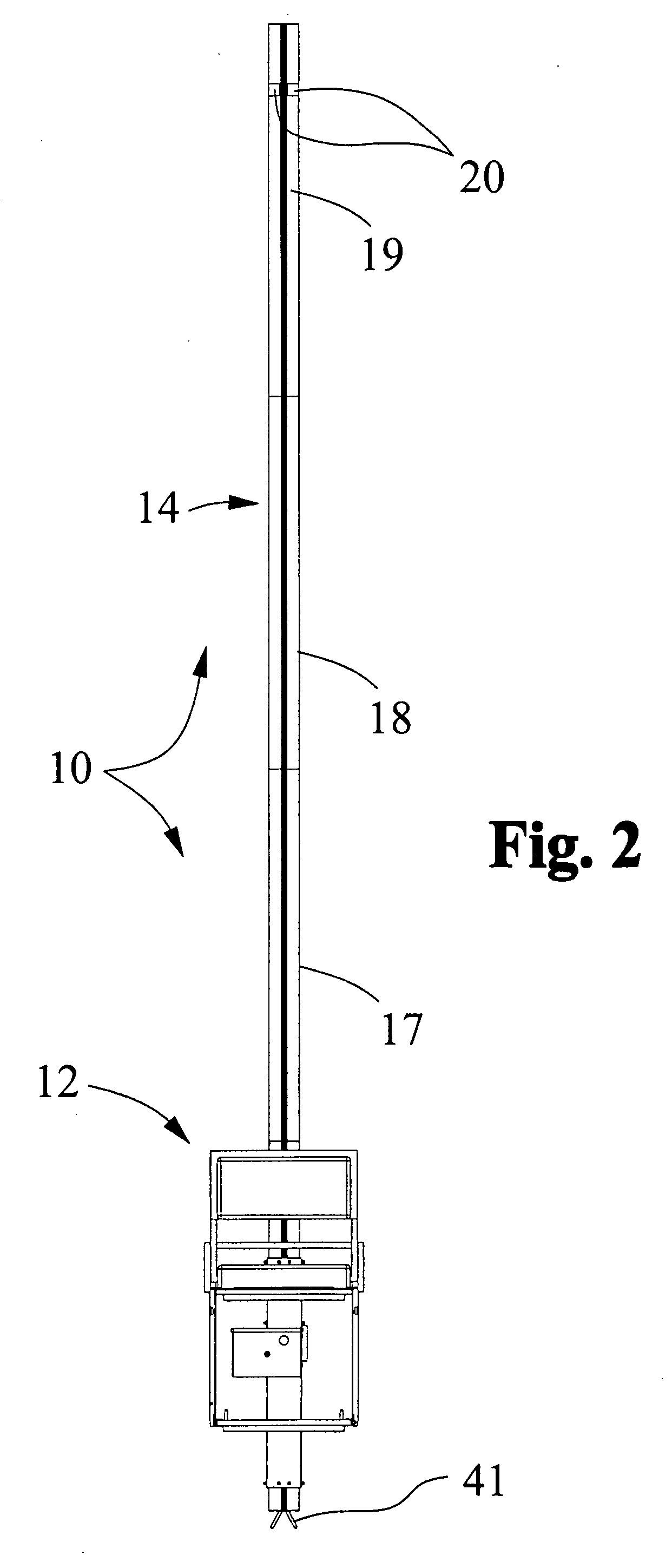
[0019]The motorized, climbing stand is ideal for hunting. An elongated, track constructed in the field from multiple, axially aligned sections, is attached to a tree trunk by suitable clamps or bands. A carriage with a comfortable seat is coupled to a shuttle assembly that engages the track. The shuttle assembly mounts a motor and a driven gear that engages the track, enabling the carriage to move vertically upwardly or downwardly in response to motor operation.
[0026]Another important object of the present invention is to provide a motorized tree stand that is simple to operate and easy to deploy.
[0027]Still another object of the present invention is to provide a deer stand of the character described that can be relatively easily disassembled and then transported.
[0031]It is another object of the present invention to provide a motorized tree stand of the character described that may be easily and efficiently assembled and deployed.
[0032]Another object of the present invention is to provide a motorized tree stand of the character described that enables a hunter to rapidly climb or descend a tree.

Problems solved by technology

However, permanent stands are difficult and time consuming to erect, and as a practical matter, they cannot be moved between hunting locations without significant time-consuming effort.
Once fastened in position, the seat cannot be easily moved vertically.
Such designs are cumbersome and difficult to deploy, especially for handicapped or elderly hunters.
When installed carelessly or inadequately, they tend to be unstable.
Often cable-driven designs require deployment, at least in part, upon an overhead branch, which can be difficult to reach, particularly when mounting the tree stand on pine trees.
Further, cable-driven power stands do not adequately brace themselves against the tree trunk, increasing the risk of falling or slipping.
Known systems involving wheels that contact the tree trunk are unstable and they tend to slip.
While some portable designs are quite rugged despite their light weight, one common problem with so-called portable stands is that they can be relatively flimsy and unstable.
On the other hand, ruggedized, heavy duty designs made of bulky metal parts tend to be heavy and cumbersome.
However, it is important to realize that the disadvantages associated with heavier tree stands are outweighed by their dexterity.
However, while a deer stand that can be carried into the woods in a single trip has obvious advantages, many hunters no longer demand such simplicity.
If a heavy duty “portable” stand that is rugged and powered can elevate the hunter automatically to an elevated position, the disadvantages associated with increased weight will be forgotten and excused.

Method used


Image

  • Motorized climbing hunting stand
  • Motorized climbing hunting stand
  • Motorized climbing hunting stand

Examples


Embodiment Construction

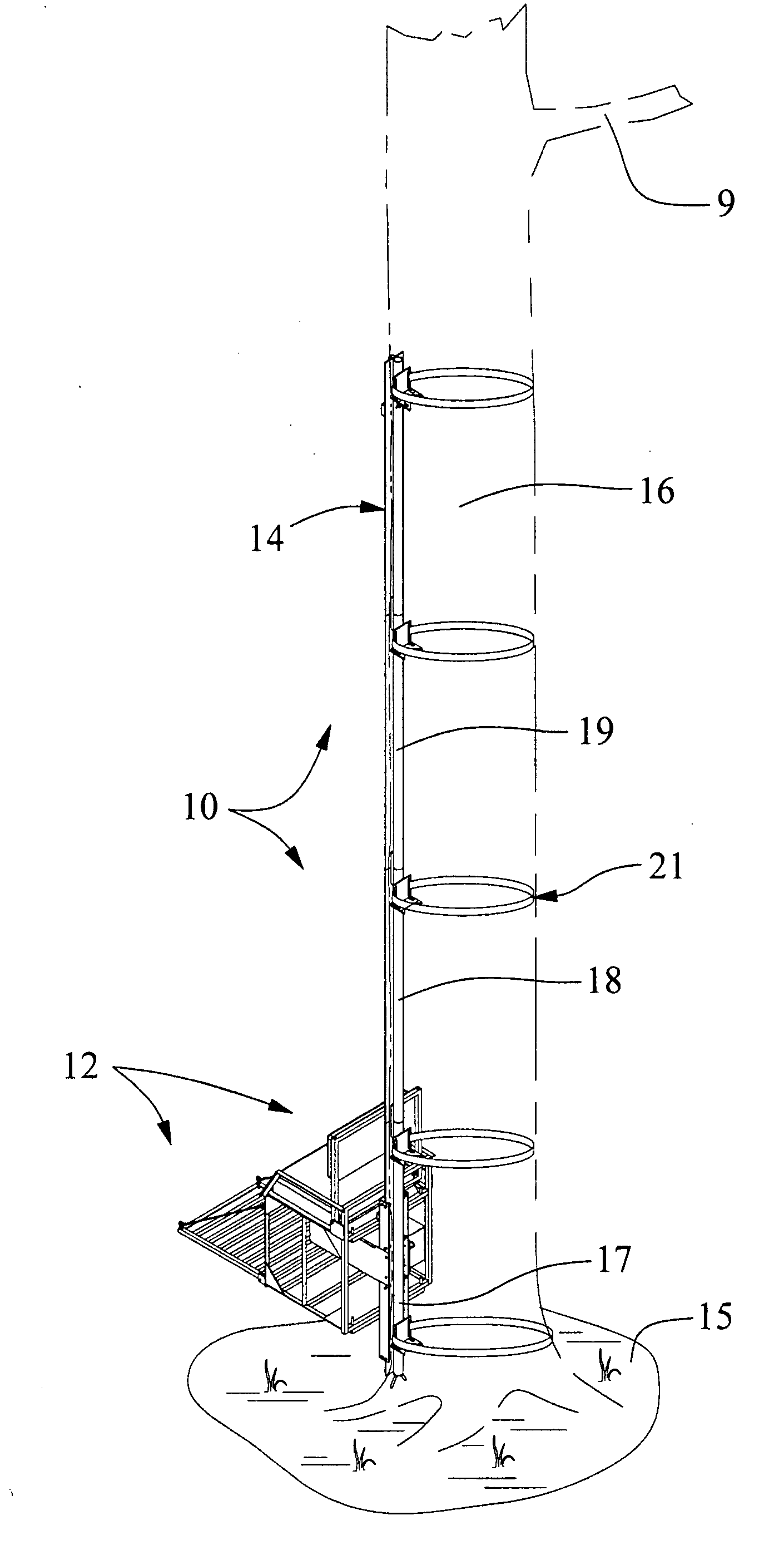
[0050]With initial reference directed now to FIGS. 1 and 2 of the appended drawings, a motorized, climbing device, constructed generally in accordance with the best mode of the invention, has been generally designated by the reference numeral 10. Preferably device 10 is in the form of a hunter's tree-climbing stand. However, the device may be used to climb any elongate, vertical column or pole that is generally cylindrical and which has a smooth lower circumference.

[0051]The tree stand embodiment is preferred. The stand 10 is illustrated in a lowered position in FIG. 1, providing access for a hunter or other passenger or user to be seated within a carriage 12 that engages a track 14. Preferably the hunting stand 10 is used by sportsmen or outdoorsmen that desire an elevated observation position for hunting, as is common practice with deer hunters. Of course the stand 10 presents numerous advantages and features that are useful to others besides hunters such as those that service tel...


PUM


Abstract

A motorized, climbing tree stand ideal for hunting has a rigid elongated, track constructed from multiple, axially aligned sections attached to a tree trunk. A carriage supporting a seat and footrest is coupled to a shuttle assembly that engages the track. The shuttle assembly mounts a battery-powered motor and a motor-driven gear that engages a toothed rack on the elongated track, moving the carriage vertically upwardly or downwardly in response to motor operation. A hand switch controls a reversing relay to control motor direction. Each track section comprises a rigid, elongated flange with an elongated, tubular sleeve terminating in a reduced diameter coupling tube that coaxially mates with the base of the sleeve in the neighboring section. Alignment rods near the upper ends of each sleeve reinforce the assembly. Adjustable, L-brackets contact the tree for bracing. Track flanges are slidably constrained between suitable rollers secured to shuttle side walls.

Description

BACKGROUND OF THE INVENTION[0001]1. Field of the Invention[0002]The present invention relates generally to elevated hunting or observation stands. More particularly, the present invention relates to hunting stands, primarily for use with trees, that transport the user to a desired elevation above ground. Known prior art stands are classified in United States Patent Class 182, Subclasses 133, 135-137, 141, and 187-188.[0003]2. Description of the Related Art[0004]Hunters have long recognized and appreciated the many advantages gained by hunting from elevated positions, especially with modern tree stands. Stands that have been properly designed and correctly deployed comfortably provide a safe, seated position at an elevation that is ideal for inconspicuously observing and bagging game animals. An elevated position amplifies the hunter's field of view, enlarging the potential target area.[0005]Numerous diverse tree stands exist in the art. Large, relatively heavy permanent stands are w...

Claims


Application Information

Patent Timeline
Patent Type & Authority Applications(United States)
IPC IPC(8): A01M31/02
CPCA01M31/02
Inventor MOTES, MICHAEL JOEL
Owner MOTES OUTDOOR EQUIP
Learn More