
Suspension system for a vehicle

a suspension system and vehicle technology, applied in the direction of resilient suspension, interconnection system, vehicle springs, etc., can solve the problems of requiring a greater spring rate of leaf springs, harsh ride for occupants and cargo of vehicles, and only using leaf springs in the suspension system to support the weight of the suspended structure, etc., to reduce the hysteresis of the leaf-spring group, reduce the weight, and reduce the spring rate

Inactive Publication Date: 2004-05-25
INT TRUCK INTPROP LLC
View PDF20 Cites 19 Cited by
  • Summary
  • Abstract
  • Description
  • Claims
  • Application Information

AI Technical Summary

Benefits of technology

The present invention provides a novel suspension system for vehicles that has low hysteresis and is composed of simple components. The suspension system includes leaf springs and pneumatic springs that work together to provide full lateral and longitudinal location of the suspended structure. The leaf springs are engaged to the structure and the pneumatic springs in a way that allows the structure to move relative to the springs in all directions except when the leaf springs deform elastically. This prevents the structure from moving relative to the springs when the leaf springs are in use. The suspension system is designed to have low hysteresis and can transmit all forces between the structure and the springs without allowing any substantial relative horizontal movements between them.

Problems solved by technology

The use of only leaf springs in a vehicle's suspension system to support the weight of the suspended structure does, however, have disadvantages as compared to the use of other types of springs for supporting the weight of the suspended structure.
Due to a combination of factors which include weight carrying requirements, limitations in the length of leaf springs due to space constraints on a vehicle, and fatigue strength of the leaf springs, the use of leaf springs as opposed to other types of springs in a vehicle suspension system often requires greater spring rates of the leaf springs than would be necessary for other types of springs if employed.
The greater spring rates that are often necessitated in a suspension system of a vehicle as a result of the use of leaf springs in lieu of other types of springs can result in a harsher ride for the occupants and cargo of the vehicle and reduced life of the suspended structure supported by the leaf springs.
One disadvantage of the use of such leaf-spring packs is that friction between each of the leaf springs and those positioned above and below it causes hysteresis in the reaction of the leaf-spring pack to changing loads.
The hysteresis in leaf-spring packs results in the same negative consequences for suspension systems that utilize them as those negative consequences associated with increased spring rates.
Most pneumatic springs that are traditionally used in suspension systems of vehicles, however, have the inherent disadvantage of being relatively weak in all modes of loading except for compression loading along axes between the support mounting-portion(s) and the supported mounting-portion(s) of the spring.
For this reason, suspension systems of vehicles that utilize only pneumatic springs to support the weight of the suspended structure generally include relatively complex arrangements of linkages, which locate the suspended structure in those directions other than compression axes of the pneumatic springs thereof.

Method used


Image

  • Suspension system for a vehicle
  • Suspension system for a vehicle
  • Suspension system for a vehicle

Examples


Embodiment Construction

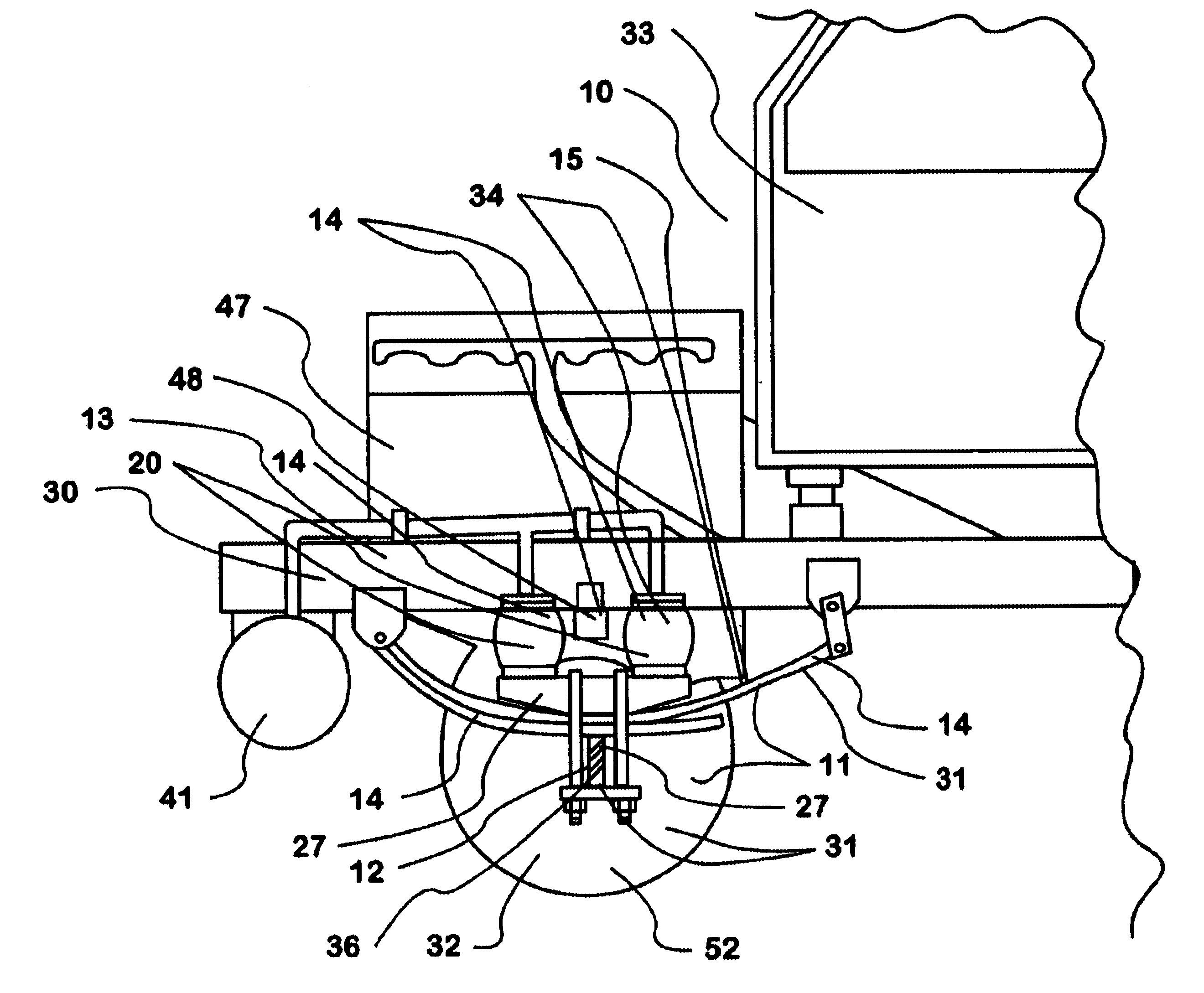
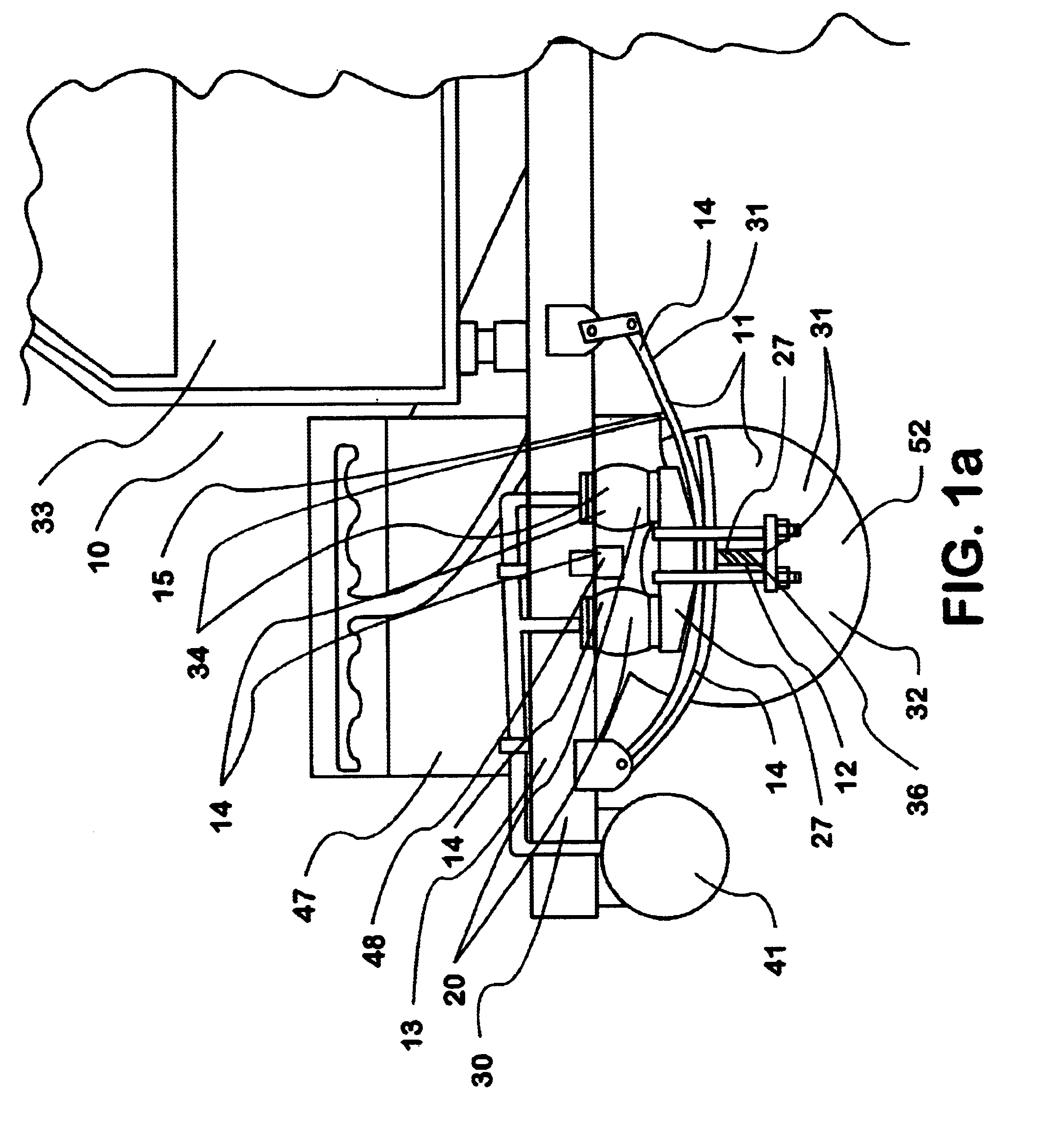
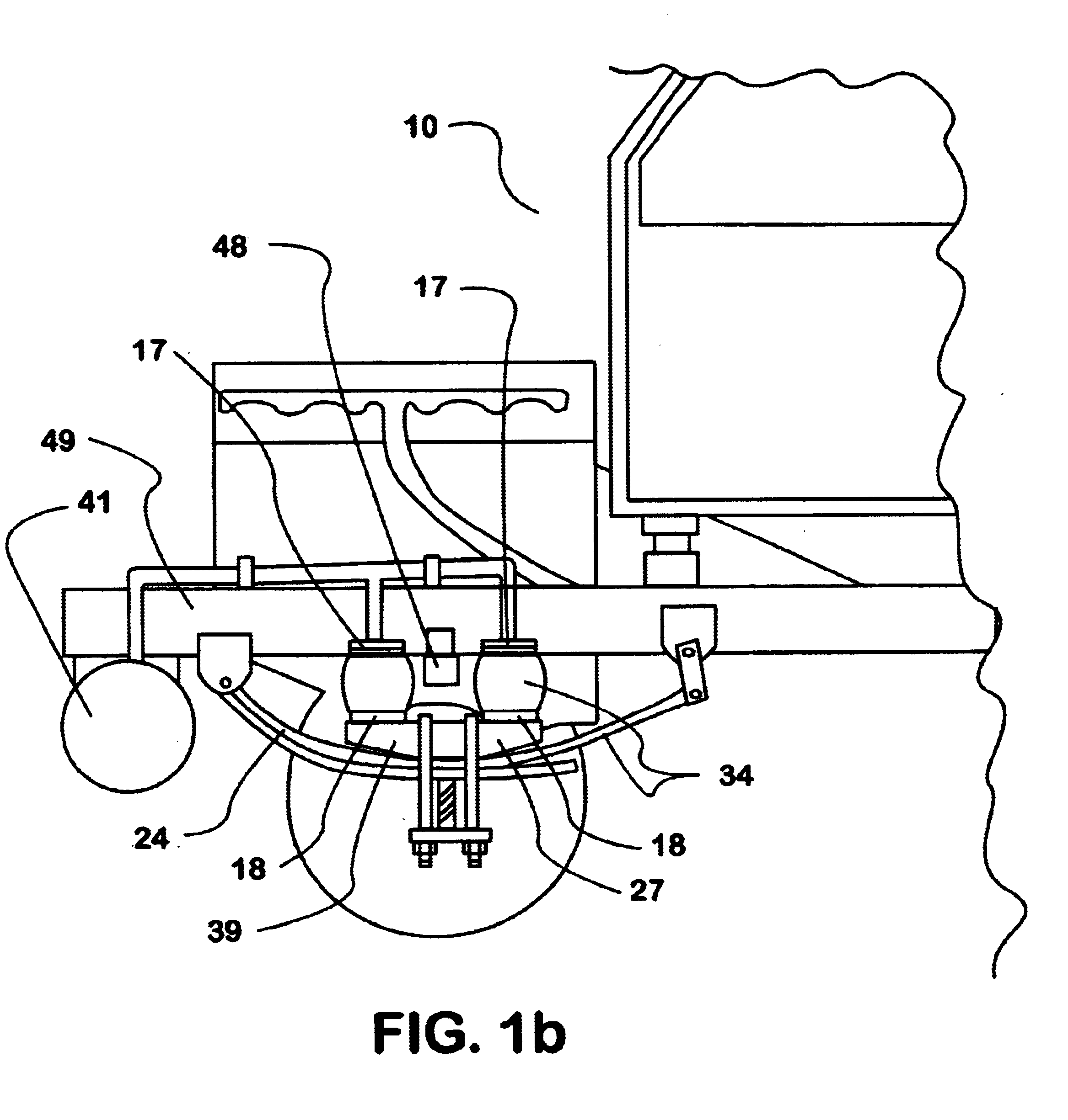
The present invention is a novel suspension-system 34 for a vehicle 10. As is shown in the drawings, such a vehicle 10 comprises one or more frame structures 30 to which a majority of other components of the vehicle 10 are directly or indirectly engaged and which provide the structural strength that maintains proper relative locations of these other components of the vehicle 10. Such a vehicle 10 also comprises a primary suspension-system 31 some part or all of which may be a novel suspension-system 34 according to the present invention. The primary suspension-system 31 of the vehicle 10 comprises one or more ground-engaging component(s) 32 such as wheel(s) 52, track(s), and / or runner(s) that move along the ground when the vehicle 10 is in motion. The primary suspension-system 31 of the vehicle 10 further comprises one or more springs 14, that are engaged between the ground-engaging component(s) and the frame structure(s) 30 of the vehicle 10, and which support the frame structure(s...


PUM


Abstract

A novel suspension-system for a vehicle has two or more leaf-spring groups that vertically support a portion of the weight of a suspended structure of the vehicle. The novel suspension-system further includes pneumatic springs that are engaged to spring-support components of the novel suspension-system and also the suspended structure supported by the novel suspension-system in such a manner that the pneumatic springs assist the leaf-spring groups of the novel suspension system in vertically supporting the weight of the suspended structure.

Description

The present invention relates to a suspension system of a vehicle. A suspension system of a vehicle being considered, for the purposes of this disclosure, to be a group of components engaged to and supported by either the ground or one or more support structure(s) and also engaged to and supporting one or more suspended structure(s). Additionally, a suspension system of a vehicle comprises one or more spring(s) that support the weight of the suspended structure(s) engaged to the suspension system. The spring(s) of a suspension system of a vehicle support the weight of the one or more suspended structure(s) that are engaged to the suspension system in a cushioned manner by flexing and allowing the suspended structure to move relative to the support structure(s) or ground, which support the suspension system, when the vertical accelerations of the suspended structure and / or the support structure change and / or when the loading of the suspended structure is changed. For instance, when a...

Claims


Application Information

Patent Timeline
Patent Type & Authority Patents(United States)
IPC IPC(8): B60G11/32B60G11/30B60G11/26B60G11/46B60G21/073B60G21/00
CPCB60G11/30B60G11/465B60G21/073B60G2200/30B60G2202/112B60G2202/114B60G2202/152B60G2202/154B60G2204/126B60G2204/82B60G2204/8304B60G2300/026B60G2202/1524
Inventor WARINNER, DEREK K.KORSON, JAMES
Owner INT TRUCK INTPROP LLC
Learn More