Molding machine

a molding machine and machine body technology, applied in the field of molding machines, can solve the problems of closing force, all the more serious, and the closing force is not applied, and achieve the effect of improving the quality of the finished produ

Inactive Publication Date: 2004-05-25
MANNESMANN PLASTICS MACHINERY
View PDF4 Cites 2 Cited by
  • Summary
  • Abstract
  • Description
  • Claims
  • Application Information

AI Technical Summary

Benefits of technology

According to the present invention, the closing force is applied by a hydraulic compressive force. However, this closing force is not applied by using a conventional hydraulic fluid, which generally consists of an oil. In contrast, the present invention applies the closing force via a composition which possesses a comparatively high viscosity. One effect of this is that the occurrence of leakages is prevented from the outset as a consequence of the considerably inferior flow properties of this composition by comparison with a conventional hydraulic fluid. Furthermore, if a leakage does occur, the highly viscous composition escapes only in comparatively small amounts, so that even when a leak is beginning to occur this can easily be identified visually. In addition, the solution according to the present invention has the advantage that even in the event of a larger amount of escaping viscous composition this does not flow away like hydraulic oil to cover a large area but remains in the area close to the point of escape.
Grease is preferably used as the highly viscous composition because of its good lubrication qualities.

Problems solved by technology

A disadvantage of hydraulically actuated plastics injection molding machines or other molding machines with high closing forces is that, to a certain extent, it is always necessary to expect a leakage of hydraulic fluid, in other words, conventionally, hydraulic oil.
This is all the more serious if the hydraulic seals become loose due to wear.
This disadvantage also occurs in what are known as hybrid machines such as the machine disclosed by DE 196 43 366 A1 in which the displacement movement of the movable mold mounting plate and the generation of the closing force are effected by different drive systems.
However, this closing force is not applied by using a conventional hydraulic fluid, which generally consists of an oil.

Method used


Image

  • Molding machine
  • Molding machine

Examples


Embodiment Construction

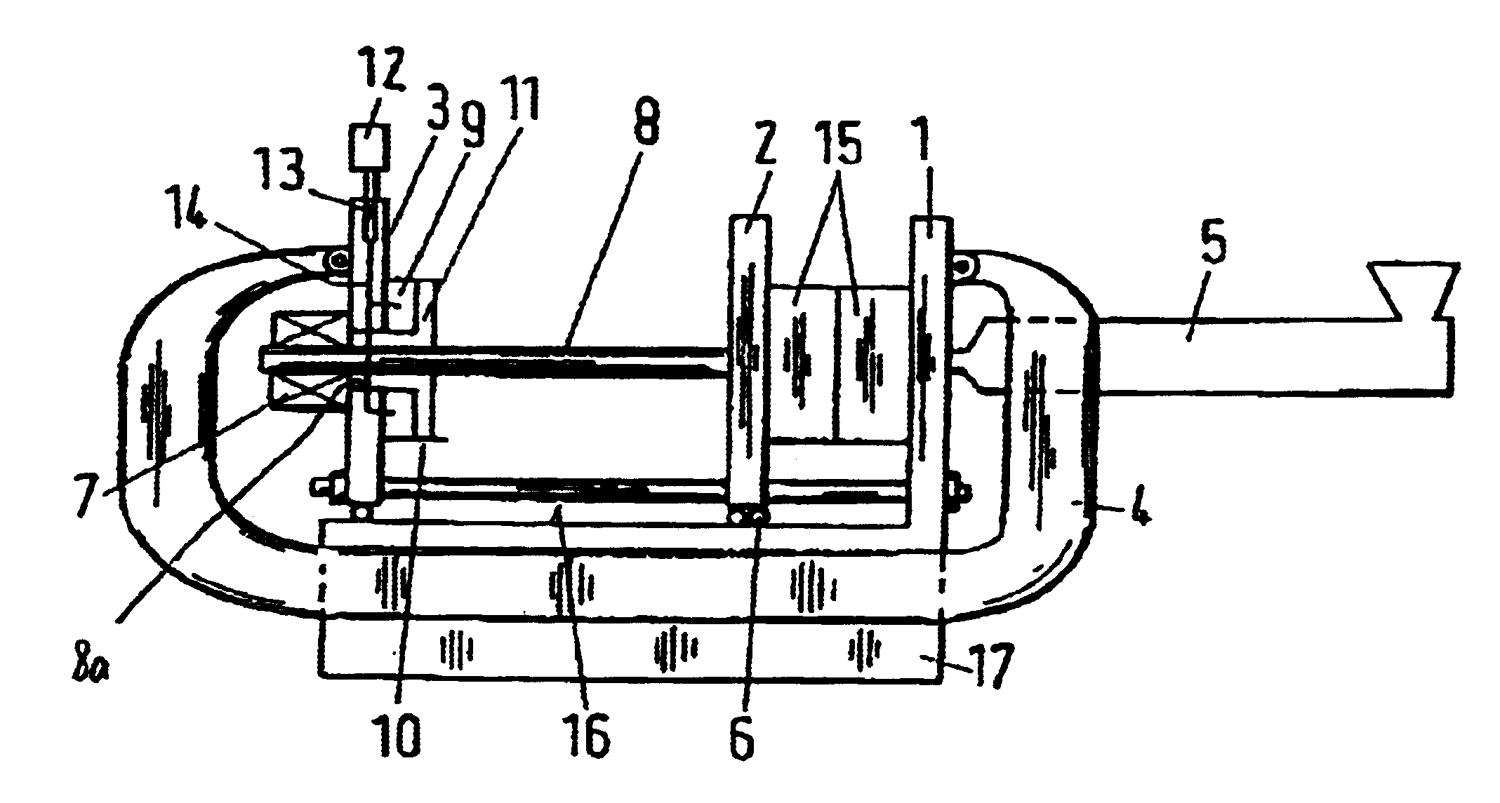
The injection molding machine shown in the drawing comprises a machine frame 17 which is rigidly connected to a fixed mold mounting plate 1. A movable mold mounting plate 2 is mounted on the machine frame so that it is linearly displaceable on a guide track 16 by rollers 6. Two halves of an injection mold 15 are disposed between the two mold mounting plates 1,2. A third plate 3 is disposed on the left-hand side of the machine frame 17. This plate 3, however, is not rigidly connected to the machine bed 17 but is mounted movably, in a similar manner to the mold mounting plate 2.

The fixed mold mounting plate 1 and the third plate 3 are held by a shackle 4, which is articulated on the back of each of the plates 1, 3. The shackle 4 is disposed on both long sides of the machine bed 17, i.e., as a pair. The shackle 4 ensures that the third plate 3 is not significantly displaced. The shackle 4 allows displacements of the third plate to occur only within an order of magnitude corresponding t...


PUM

PropertyMeasurementUnit
viscosityaaaaaaaaaa
pressureaaaaaaaaaa
viscousaaaaaaaaaa

Abstract

A molding machine includes a mold space between two mold carriers. One of the two mold carriers is movable relative to the other by a drive. A separate power unit generates a predetermined closing force between the two mold carriers when the two mold carriers are moved together. The separate power unit comprises, for its actuation, a pressure cushion filled with a composition that is highly viscous by comparison with hydraulic oil.

Description

1. Field of the InventionThe invention relates to a molding machine formed as a press for the production or reshaping of pressings or as an injection molding machine for the injection molding of plastics and having a mold space between two mold carriers, wherein one of the mold carriers is movable relative to the other by a drive.2. Description of the Related ArtAn injection molding machine conventionally comprises two mold halves which are fixed to mold mounting plates and have to be pressed toward one another with great force during the injection of the current molding composition into the mold cavity to ensure that the injected material does not escape through area where the two mold mounting plates are joined. Conventionally, one of the two mold mounting plates is rigidly connected to a machine frame, while the second mold mounting plate is linearly displaceable for the purpose of unmolding each injection molding produced. Therefore, a system such as , for example, a hydraulic c...

Claims


Application Information

Patent Timeline
Patent Type & Authority Patents(United States)
IPC IPC(8): B29C45/68B29C45/17B29C45/64
CPCB29C45/1761B29C45/68B30B15/047B29C2045/1768
Inventor FISCHBACH, GUNTHER
Owner MANNESMANN PLASTICS MACHINERY
Why Eureka
Try Eureka