Composite wheel for tracked vehicles

a technology for track vehicles and composite wheels, which is applied in the direction of manufacturing tools, furnaces, heat treatment equipment, etc., can solve the problem that the problem of manufacturing wheels from a unitary base material is not necessarily desirabl

Inactive Publication Date: 2004-06-08
XTEK
View PDF22 Cites 11 Cited by
  • Summary
  • Abstract
  • Description
  • Claims
  • Application Information

AI Technical Summary

Problems solved by technology

Therefore, manufacturing the wheel from a unit

Method used


Image

  • Composite wheel for tracked vehicles
  • Composite wheel for tracked vehicles
  • Composite wheel for tracked vehicles

Examples


Embodiment Construction

Although the following description specifically describes the present invention as being applied to a single flanged wheel typically used on railroad vehicles and / or any other transport vehicle, the invention is to be understood as being equally applicable to dual flanged steel wheels as typically used on rail guided industrial, crane type, vehicles.

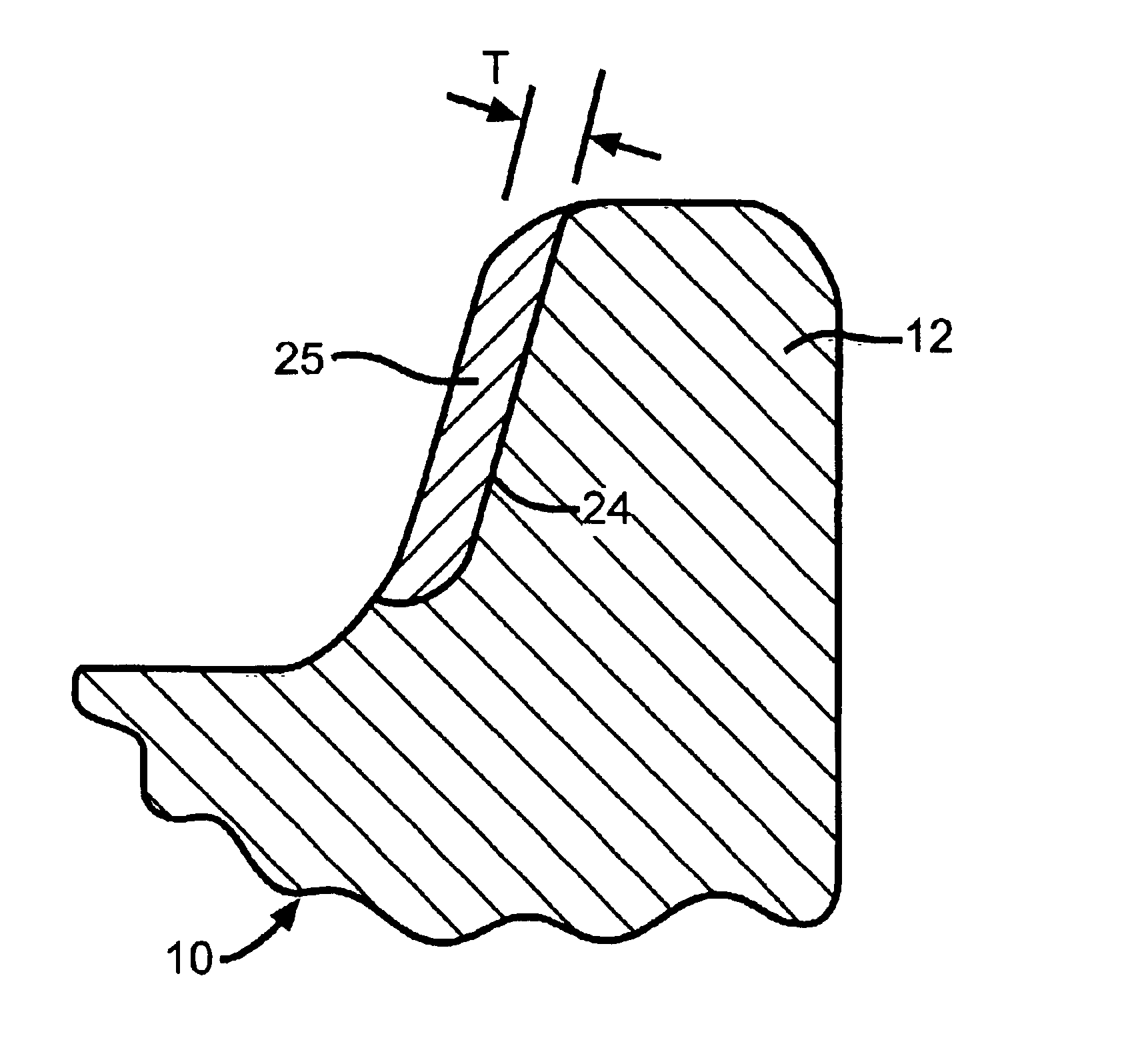
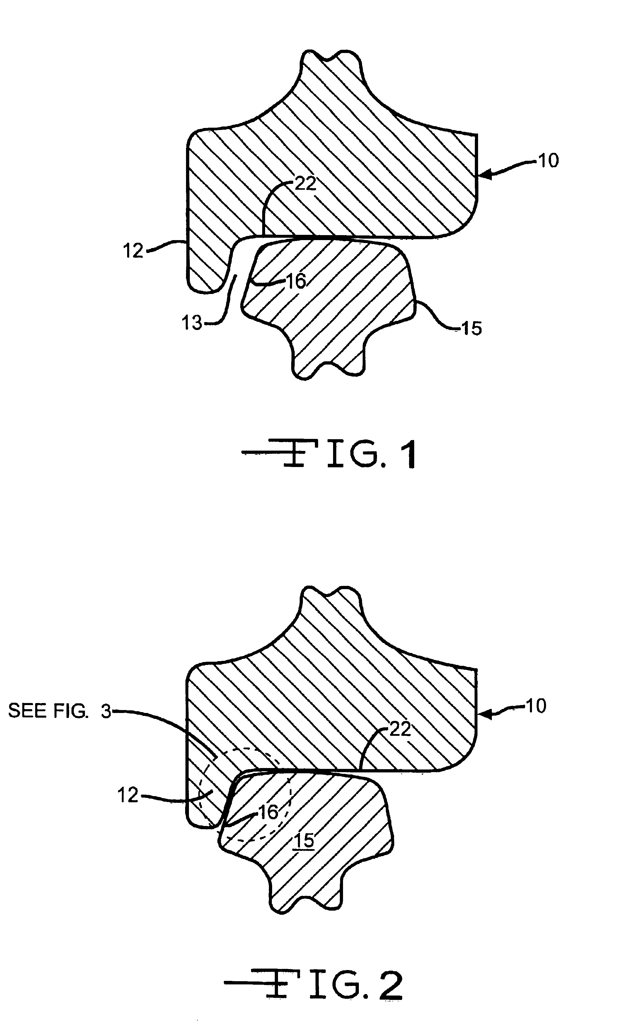
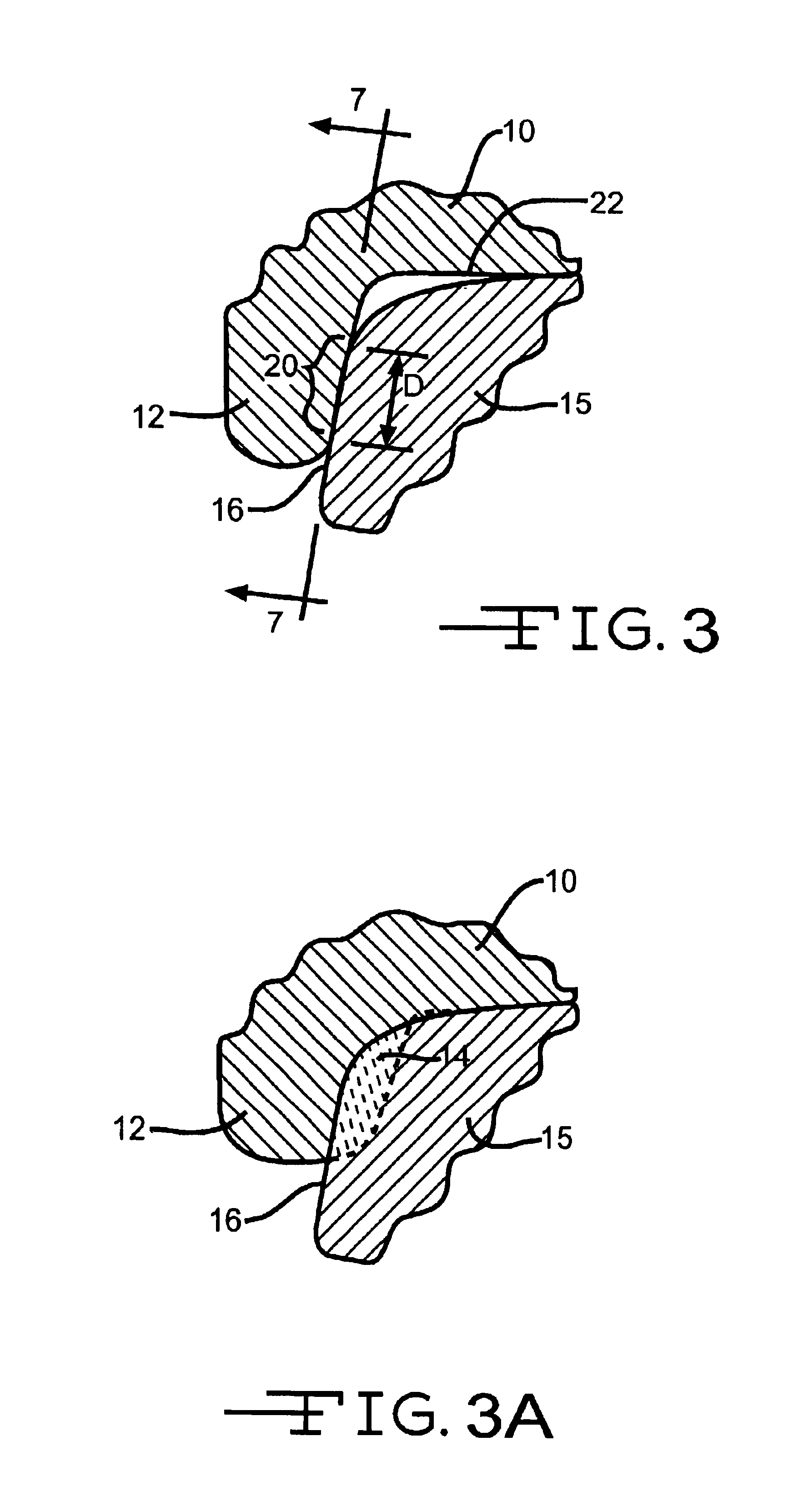
FIG. 1 illustrates a partial crossectional view of a typical dual flanged steel wheel 10, having a single flange 12, in rolling contact with a typical guide rail 15. Under ideal conditions a clearance 13 exists between the wheel flanges 12 and rail 15, whereby rail-wheel contact only exists between the top of the rail 15 and the wheel's tread 22.

However many times, because of asymmetrical loading of the tracked vehicle or defects in rail alignment, the wheel flange may frequently engage the rail side face 16 thereby causing frictional engagement between rail flange 12 and the rail side face 16 as illustrated in FIGS. 2 and 3. Such fricti...


PUM

PropertyMeasurementUnit
Shapeaaaaaaaaaa
Frictionaaaaaaaaaa

Abstract

The present invention relates to a method of manufacturing an all metal, single or dual, flanged composite railroad wheel for rollingly engaging a metal rail. A unitary metal railroad wheel having at least one radially extending wheel flange, for intermittently engaging the side surface of the rail, is provided with a metallic inlaid material having a coefficient of friction lower than the coefficient of friction of the wheel's main body. The inlaid low friction material forms an annular band circumscribing the inside surface of the wheel's radially extending flange.

Description

The present invention generally relates to a flanged steel wheel having either single or dual flanges as typically used on tracked transportation vehicles such as railway locomotives and rolling stock, shipyard and port gantry cranes, industrial bridge cranes, mining cars transit cars or any other material handling or transportation application. More specifically the present invention relates to an improved composite structure for the flanged portion of both single and dual flanged wheels.Although the present invention is equally applicable to single flanged steel wheels, it is particularly useful on dual flanged steel wheels typically used in industrial gantry and bridge cranes that traverse fixed, parallel rails, of finite length. In such industrial applications, because of the typical asymmetrical loading of the gantry or bridge crane, the vertical plane of the flanged wheel frequently becomes askew to the direction of the rails whereby the wheel flange contacts the side of the r...

Claims


Application Information

Patent Timeline
IPC IPC(8): B60B17/00
CPCB60B17/0003B60B17/0068Y10T29/49483
Inventor PETREK, FRANK P.SHAFFER, STEVEN J.
Owner XTEK
Why Eureka
Try Eureka