
Convertible road and rail wheel assembly

Inactive Publication Date: 2005-10-13
4 RAILER
View PDF29 Cites 9 Cited by
  • Summary
  • Abstract
  • Description
  • Claims
  • Application Information

AI Technical Summary

Problems solved by technology

Various hydraulic devices have been used to assist crews in removing and replacing section cars on tracks, a very time consuming and inefficient process.
Further, the hydraulic devices increase cost of the cars and their maintenance.
Some section cars can be removed and replaced on rails manually, but this task requires substantial effort by the crew and puts the crew at risk of injury.
The modifications are relatively expensive.
However, substantial time is required to transfer the vehicle to rails since the vehicle must be turned perpendicular to the passage of vehicles on the intersecting highway.
In addition, once these vehicles are at a location remote from a grade crossing, it is difficult, if not impossible, to remove the vehicle from the rails to allow a train to pass.
This difficulty in keeping the track clear interferes with rail traffic, causing substantial inefficiency in railroad operations.
However, the vehicles cannot be used directly in a railroad system.
Therefore, adjusting vehicles with these wheel structures to different rail gauges is extremely complicated.
Accordingly, each vehicle not originally manufactured for railway use and employing these two kinds of wheels requires special and expensive modification.

Method used


Image

  • Convertible road and rail wheel assembly
  • Convertible road and rail wheel assembly
  • Convertible road and rail wheel assembly

Examples


Embodiment Construction

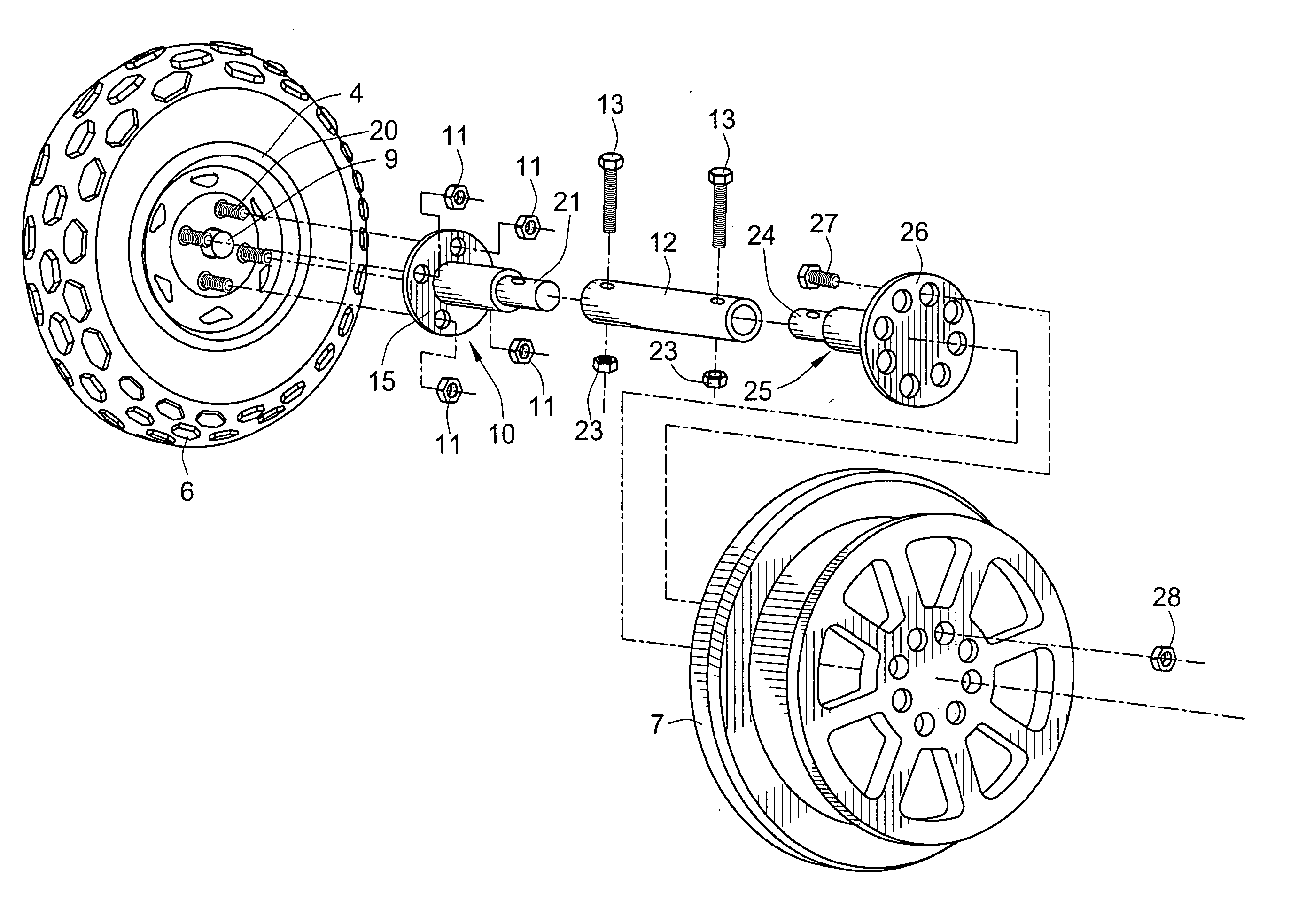
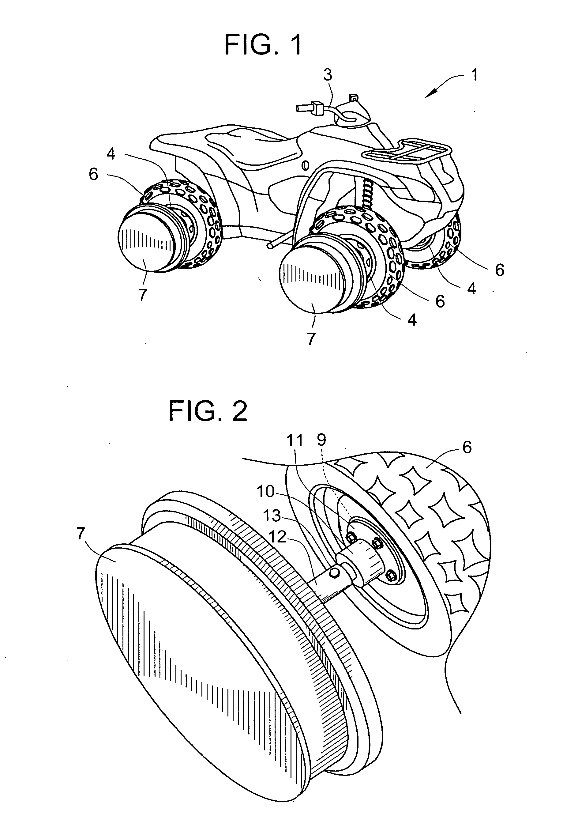
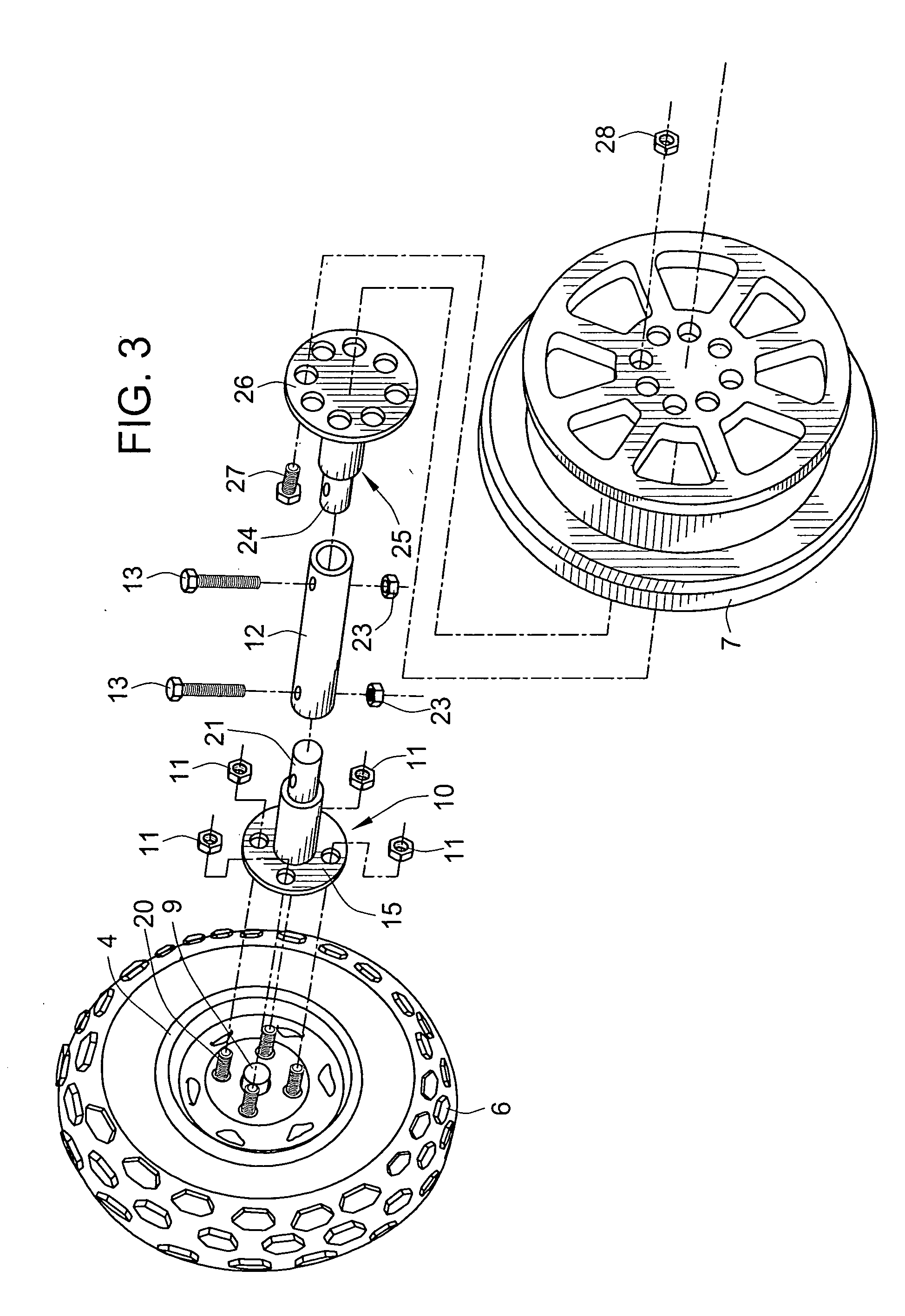
[0025]FIG. 1 is perspective view of a vehicle 1 according to the invention. The basic vehicle shown is an example of a commercially available gasoline-powered self-propelled ATV intended for a single rider. However, the invention encompasses other similar four-wheeled ATV and utility vehicles that accommodate two or more persons and that include space for carrying some cargo. The vehicle includes a steering mechanism that, in the illustrated embodiment, includes handlebars 3, for steering two of the four wheels 4 of the vehicle 1. In a conventional way, the handlebars control the angle of the front wheels. The rear wheels are not steered. As shown in FIG. 1, the tires 6 are mounted on each of the front and rear wheels 4, including the rear wheel that is not visible in FIG. 1. In addition, a rail wheel 7 is mounted on each of the hubs 9 (not visible in FIG. 1) of the axles of the vehicle. The front and rear wheels 4 are also mounted on the respective hubs 9. The wheels 4 and the tire...


PUM


Abstract

A self-propelled four-wheel vehicle (1) for travel on land and / or on rails includes four hubs (9) for mounting of wheels including tires (6) for travel on land, four rail wheels (7) for travel on a railway, and four coupling assemblies, for detachably connecting the rail wheels to, outwardly of, and spaced from, the hubs. A kit for converting the vehicle for travel on rails includes, for each hub (9) of the vehicle, a rail wheel adapter (25, 44) including a flange (26, 45) for fastening to a rail wheel (7) and an axle portion (24, 46) extending transverse to the flange, a vehicle wheel adapter (10, 40) including a flange (15, 41) for fastening to a hub of the land vehicle and an axle portion (21, 42) extending transverse to the flange, and a coupler (12, 13) for coupling the rail wheel adapter to the vehicle wheel adapter.

Description

[0001] This application claims the benefit of U.S. Patent Application 60 / 382,566, filed May 24, 2002, the disclosure of which is incorporated herein by reference.FIELD OF THE INVENTION [0002] This invention relates to vehicles that can travel on both land and on a railroad and to a kit for converting a land vehicle so that the vehicle can travel both on land and on a railroad. BACKGROUND OF THE INVENTION [0003] For many years railroads have employed small vehicles for inspecting railroad tracks and for transporting maintenance crews to locations on railroad tracks where repair and / or maintenance is needed. Since only a few persons, a section crew, are required to perform many small maintenance tasks and inspections, small rail vehicles carrying a few persons to remote locations are needed. In most locations only a single railroad track is available so that, ideally, the vehicle transporting the section crew can be easily removed from railroad tracks at the site of maintenance to all...

Claims


Application Information

Patent Timeline
IPC IPC(8): B60B19/02
CPCB60B19/02
Inventor MEYER, DAMON
Owner 4 RAILER
Learn More