Railway wheels monitoring system and method

a technology for monitoring systems and railway wheels, applied in the direction of instruments, electrical equipment, image data processing, etc., can solve the problems of train losing contact with these elements, severe damage, and potentially affecting the logistics contract, and achieve the effect of suffering wear

Active Publication Date: 2018-08-09
VALE LIMITED
View PDF6 Cites 11 Cited by
  • Summary
  • Abstract
  • Description
  • Claims
  • Application Information

AI Technical Summary

Problems solved by technology

Train derailment it is generally caused due to loss of friction between the railway wheels and the rails, causing the train to lose contact with these elements.
This loss of friction causes the train to get off the rails, causing accidents and severe damages due to the large dimensions and high mass of the train.
Finally, a derailment potentially affects the logistics contract, which may have financial implications due to loss of cargo or even loss of life resulting from rail accidents.
The main causes of train derailment are: wheels / rails interaction, broken rails, weld failures, rail geometry imperfections, rail gauge failure, and broken wheels.
In other words, broken rails, gauge failure, rail geometry, and weld failure may directly or indirectly affect the “wheels / rails interaction”.
To name one example, a damaged railway wheels profile can cause rail geometry failures and surface imperfections, which in turn lead to excessive wheel wear.
However, this method requires a very long execution time and is subject to human failures, since the verification is manually performed by the workers.
Furthermore, because verifications occur in a periodic basis, there is a great risk of a wheel suffering excessive wear or deformation over the period between verifications.
However, said method allows only a measurement of the wheels by means of the images obtained by the device, not being possible to compare them with other wheels in perfect condition or with an ideal wheel model to determine the effective wear of the wheel.
The method described in the American document also does not allow to verify dimensions not captured by the cameras or sensors, such as the surface of wheels that is in contact with rails, making it impossible to check for anomalies in this section of the wheel and verify the wheel / rail interaction.
Moreover, the device does not allow using only cameras, requiring the application of laser sensors to perform the modeling of the wheel being monitored, thus increasing the cost of the device.
However, such device and method do not allow measuring the surface of the rail wheel, only measuring the wheel profile, preventing the identification of deformations on the wheel surface, such as protrusions, surface irregularities, and other types of problems.
Since it does not allow measuring the wheel surface, the method described also prevents the verification of the wheel / rail interaction, which can generate direct costs such as accidents and indirect costs such as excessive fuel consumption and passenger discomfort.
Furthermore, the method disclosed in US20140285658 only allows comparison of the wheel models measured by the device with other wheel models also obtained by the device, being not possible to introduce an ideal wheel model to measure the effective wear of the wheel.
Thus, it is concluded that both the periodic technique of monitoring rail wheels and the devices and systems disclosed in the state of the art are not able to effectively verify the wheel surface, thus preventing the verification of the wheel / rail interaction.
Further, none of the devices, systems, and methods in the state of the art are capable of measuring effective wear of the wheel surface and profile, comparing it with an ideal wheel model.

Method used


Image

  • Railway wheels monitoring system and method
  • Railway wheels monitoring system and method
  • Railway wheels monitoring system and method

Examples


Embodiment Construction

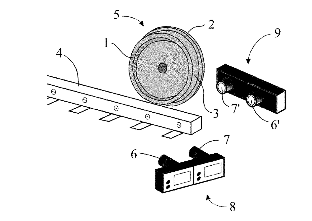
[0043]The present invention describes a system and method for the monitoring of railway wheels 5. Such monitoring makes it possible to visualize and analyze both the wheel profile 5 and its surface 3.

[0044]In addition, monitoring also allows analyzing the entire profile and surface 3 of the railway wheels 5, comparing it with an ideal wheel model to measure its effective wear.

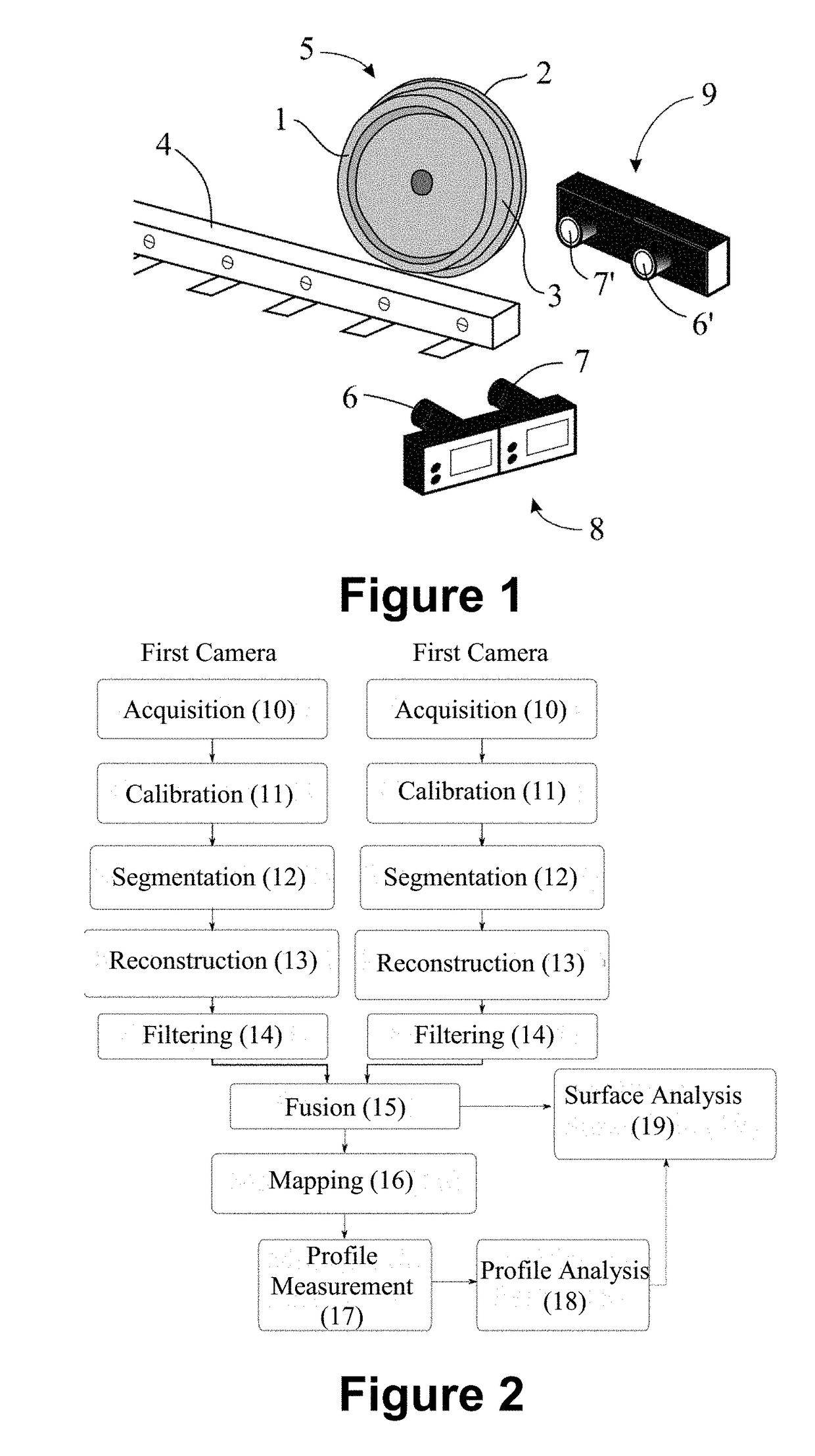
[0045]Monitoring can be divided into three fundamental steps: measuring the profile 17 of the wheel 5; analyzing the profile 18 of the wheel 5; and analyzing the surface 19 of wheel 5.

[0046]The first aspect relates to the provision of measurements relative to the geometry of the wheel 5. Regarding the analysis of the profile 18 of the wheel 5, in this step its geometry is analyzed along its entire profile, and this profile is generated only with two dimensions (2D).

[0047]The analysis of the surface 19 of the wheel 5 involves extending this process along the profile of the wheel 5 (2D) to a small region of the s...


PUM


Abstract

It is described a system and method to monitor railway wheels, which includes obtaining images of the railway wheel by means of stereo cameras and performing a three-dimensional and two-dimensional model of the railway wheel by means of these images. This two-dimensional model is subjected to analysis of the profile of the railway wheel, comparing it with a two-dimensional model of an ideal wheel and thus measuring the effective wear of its profile. The three-dimensional model is subjected to analysis of the surface of the railway wheel, also comparing it with a three-dimensional model of an ideal wheel and thus measuring the effective wear of its surface.

Description

FIELD OF THE INVENTION[0001]The present invention relates to a system and method for monitoring of railway wheels.BACKGROUND OF THE INVENTION[0002]Railway wheels consist of wheels used in vehicles that move on rails. Such vehicles are used, for example, for the transport of materials and people.[0003]The most common vehicle to use this type of wheel is a railway train, which is interconnected to several cars classified according to what is being transported. When the train transports passengers, it is named passenger train; when transporting materials, it is named freight train.[0004]Out of the aspects that are studied and analyzed in a railway system, the most important, and of interest, are: train derailment; maintenance costs; and efficient logistics strategies.[0005]Train derailment it is generally caused due to loss of friction between the railway wheels and the rails, causing the train to lose contact with these elements.[0006]This loss of friction causes the train to get off ...

Claims


Application Information

Patent Timeline
Patent Type & Authority Applications(United States)
IPC IPC(8): B61K9/12G06K9/00G06T19/20H04N13/204G06T7/00G06T7/80G06T7/62
CPCB61K9/12G06K9/00771G06T19/20H04N13/204G06T7/001G06T7/85G06T7/62G06T2207/10012G06T2207/30164H04N13/246H04N13/239G06T2207/10028G01N21/952G01N21/8851G01N2021/8887G01B11/24G01M17/10G06T7/55G06T7/97G01B11/00G06V20/52
Inventor GOMES, ANA CLAUDIA DA SILVABOTELHO DE SOUZA, CLEIDSON RONALDGARIBAY, ADAN SALAZARGUTIERREZ, ANDRES HERNANDEZ
Owner VALE LIMITED
Why Eureka
Try Eureka