Generalized clutter tuning for bistatic radar systems

a bistatic radar and generalized clutter technology, applied in the field of radar systems, can solve the problems of difficult to detect "slow moving" targets (targets, doppler shifts) in surface clutter, and not free to be optimized

Inactive Publication Date: 2004-06-08
RAYTHEON CO
View PDF4 Cites 24 Cited by
  • Summary
  • Abstract
  • Description
  • Claims
  • Application Information

AI Technical Summary

Problems solved by technology

With conventional airborne monostatic radar systems, it is often difficult to detect "slow moving" targets (targets which generate low Doppler shifts) in surface clutter due to the clutter Doppler spread resulting from the varying Doppler shifts of the terrain illuminated by the radar transmit beam.
This motion is usually fixed due to system constraints and is not free to be optimized.
For bistatic radar systems, however, the clutter Doppler spread is due to the combined motion of both the transmitter and receiver which are mounted on separate platforms.
The practical problem is how to oppose the motion of the transmitter and receiver so as to achieve substantial clutter condensation, when the t...

Method used


Image

  • Generalized clutter tuning for bistatic radar systems
  • Generalized clutter tuning for bistatic radar systems
  • Generalized clutter tuning for bistatic radar systems

Examples


Embodiment Construction

Illustrative embodiments and exemplary applications will now be described with reference to the accompanying drawings to disclose the advantageous teachings of the present invention.

While the present invention is described herein with reference to illustrative embodiments for particular applications, it should be understood that the invention is not limited thereto. Those having ordinary skill in the art and access to the teachings provided herein will recognize additional modifications, applications, and embodiments within the scope thereof and additional fields in which the present invention would be of significant utility.

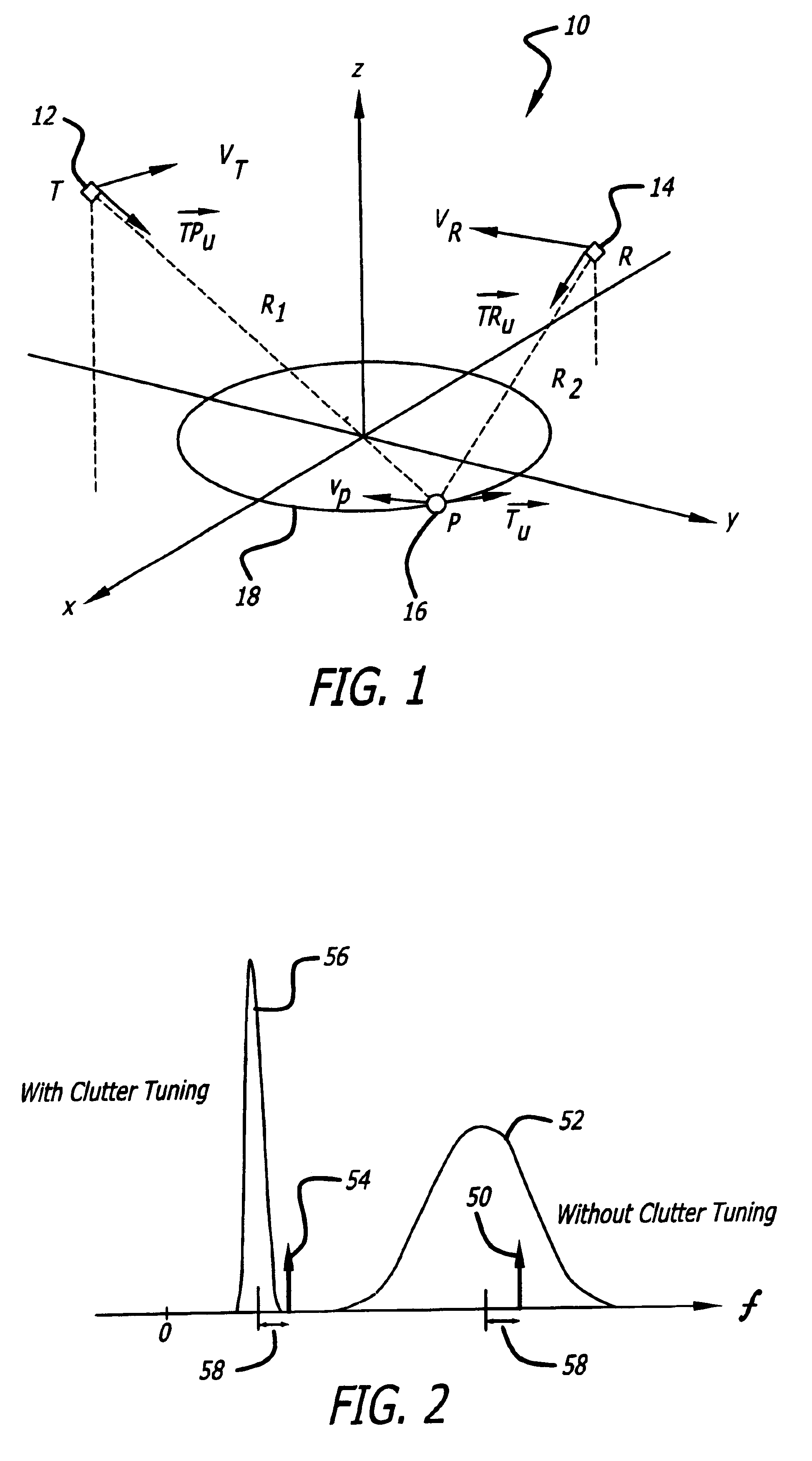
FIG. 1 is a diagram showing a transmitter-receiver-target geometry for an illustrative embodiment of a bistatic radar system implemented in accordance with the teachings of the present invention. The bistatic radar system 10 includes a transmitter 12 at a point T moving at a transmitter velocity vector v.sub.T, a receiver 14 located at a point R moving at a rece...


PUM


Abstract

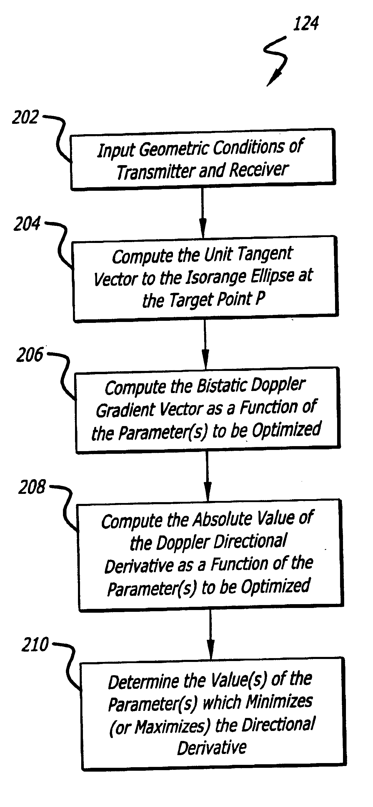
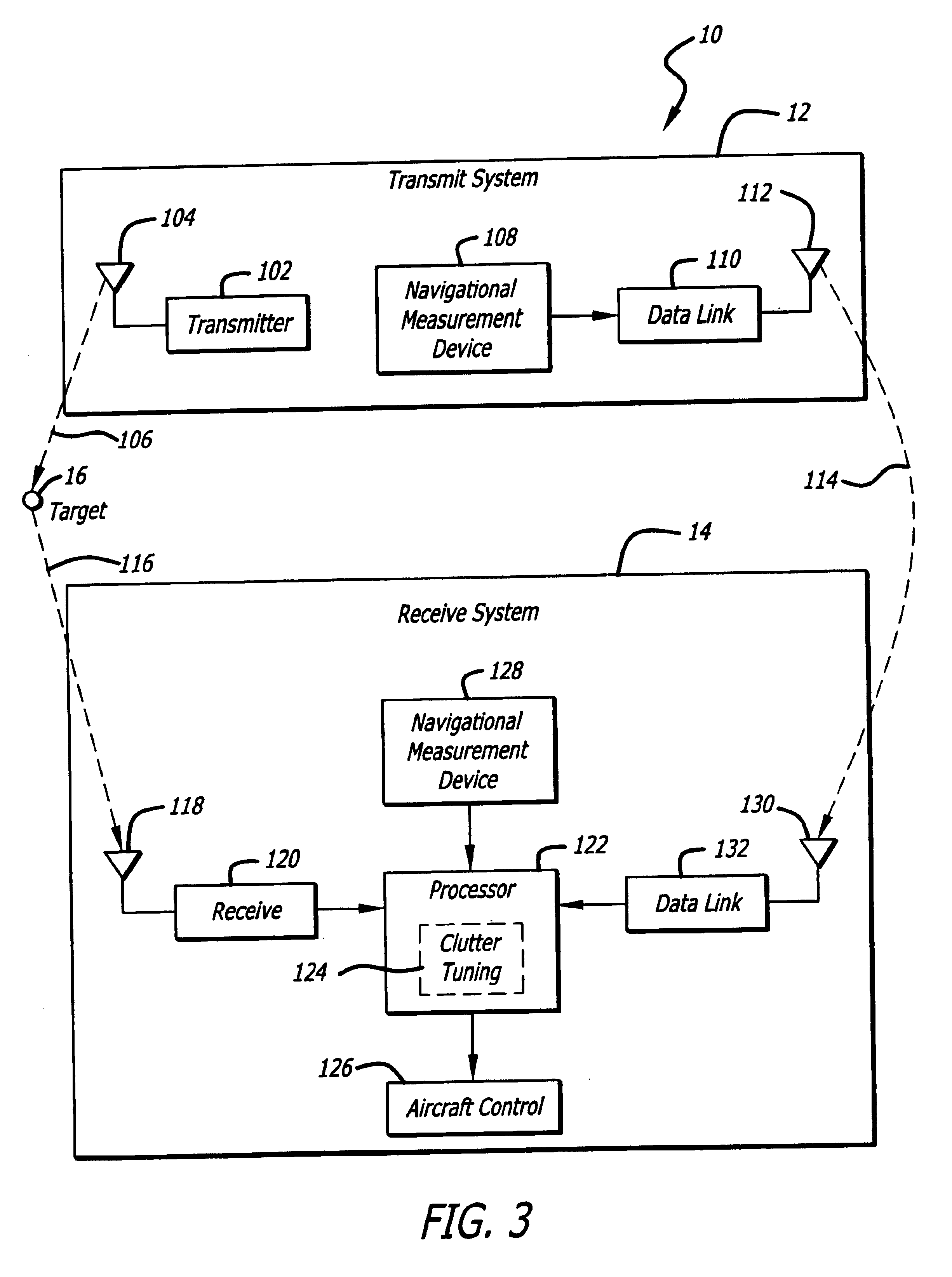
A system and method for controlling clutter Doppler spread in a bistatic radar system is developed resulting in enhanced detection of low-Doppler targets or improved SAR mode performance. In an illustrative embodiment, a bistatic radar system (10) includes a transmitter (12) for transmitting electromagnetic energy (106) towards a target (16), a receiver (14) adapted to receive the electromagnetic energy (116) reflected from the target (16), and a processor (122) for optimizing a parameter or parameters of the system such that the directional derivative of the bistatic Doppler field along the isorange contour is near a desired value. The parameters to be optimized may include the transmitter velocity vector, the receiver velocity vector, or the receiver azimuth flight direction. The desired value is the minimal absolute value of the directional derivative in order to minimize the clutter Doppler spread, or the maximum absolute value of the directional derivative in order to maximize the clutter Doppler spread.

Description

1. Field of the InventionThe present invention relates to radar systems. More specifically, the present invention relates to bistatic radar systems.2. Description of the Related ArtIn a monostatic radar system, the transmitter and the receiver are co-located. In a bistatic radar architecture, the transmitter and receiver are substantially separated. In addition, both the transmitter and the receiver may be mounted on either fixed or moving platforms. Bistatic radar is therefore distinguished from monostatic radar where the transmitter and receiver are mounted on the same platform and move together.When the transmitter and / or the receiver is in motion, the reflected signal will be Doppler frequency shifted as a function of relative motions and positions of the transmitter and receiver and the position of the target. In effect, the motions and positions of the transmitter and receiver paint the landscape with a spatial Doppler frequency gradient. If the target is also in motion, its r...

Claims


Application Information

Patent Timeline
IPC IPC(8): G01S13/524G01S13/00G01S13/90
CPCG01S13/003G01S13/524G01S13/9035G01S13/9029G01S13/9058
Inventor JAFFER, AMIN G.
Owner RAYTHEON CO
Why Eureka
Try Eureka