Afocal position detection system and ophthalmic instrument employing said system

a technology of optical position detection and ophthalmology, which is applied in the field of optical position detection system and ophthalmology instrument employing said system, can solve the problems of system too slow for use in smaller hand-held ophthalmology instruments, system of u.s. patent no. 4,881,807 and other prior art systems like it are expensive to manufactur

Inactive Publication Date: 2004-06-15
REICHERT
View PDF15 Cites 21 Cited by
  • Summary
  • Abstract
  • Description
  • Claims
  • Application Information

AI Technical Summary

Benefits of technology

It is another object of the present invention to provide a position detection system for an ophthalmic instrument that is relatively inexpensive to manufacture.
It is yet another object of the present invention to provide a position detection system for an ophthalmic instrument and a method for calibrating the system, whereby the system can be calibrated easily and periodically after manufacture to ensure accuracy.
A "heads-up" display is preferably connected to receive the X-Y-Z position data and provide instructional cues to the operator for moving the instrument to achieve alignment. In a current embodiment, the heads-up display comprises a polar array of light emitting diodes selectively illuminated to indicate a desired X-Y movement direction, and a linear array of light emitting diodes selectively illuminated to indicate a desired Z movement direction. An image of the heads-up display is presented to the operator along the instrument optical axis through the use of a beamsplitter that allows a macro-image of the patient's eye to be transmitted as well along the optical axis, whereby the X-Y polar array is arranged circumferentially about the macro-image.

Problems solved by technology

While the system described above has proved suitable for use in large table mounted instruments where the patient's head is stabilized by a forehead rest to minimize inadvertent relative movement between the instrument and the eye, the fact that a large number of CCD pixels must be scanned to make a single position determination introduces a limitation as to the repetition rate of the system that makes the system too slow for use in smaller hand-held ophthalmic instruments, where inadvertent relative motion between the instrument and the eye is constantly taking place as the operator aligns the instrument by hand.
Moreover, the system of U.S. Pat. No. 4,881,807 and other prior art systems like it are expensive to manufacture because of the types and number of optical and opto-electronic elements necessary, and the dimensional criticality in positioning these elements with respect to one another.

Method used


Image

  • Afocal position detection system and ophthalmic instrument employing said system
  • Afocal position detection system and ophthalmic instrument employing said system
  • Afocal position detection system and ophthalmic instrument employing said system

Examples


Embodiment Construction

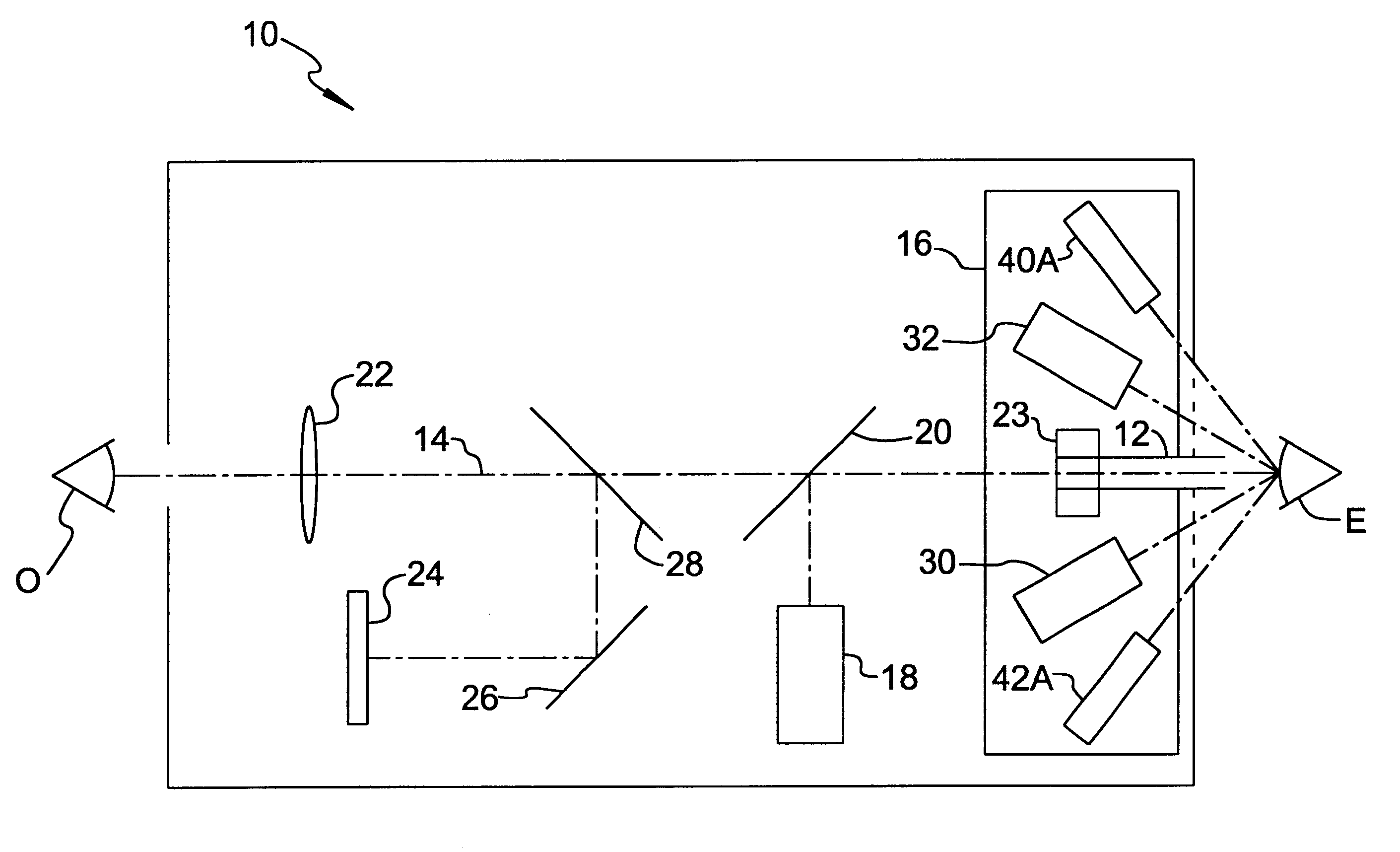
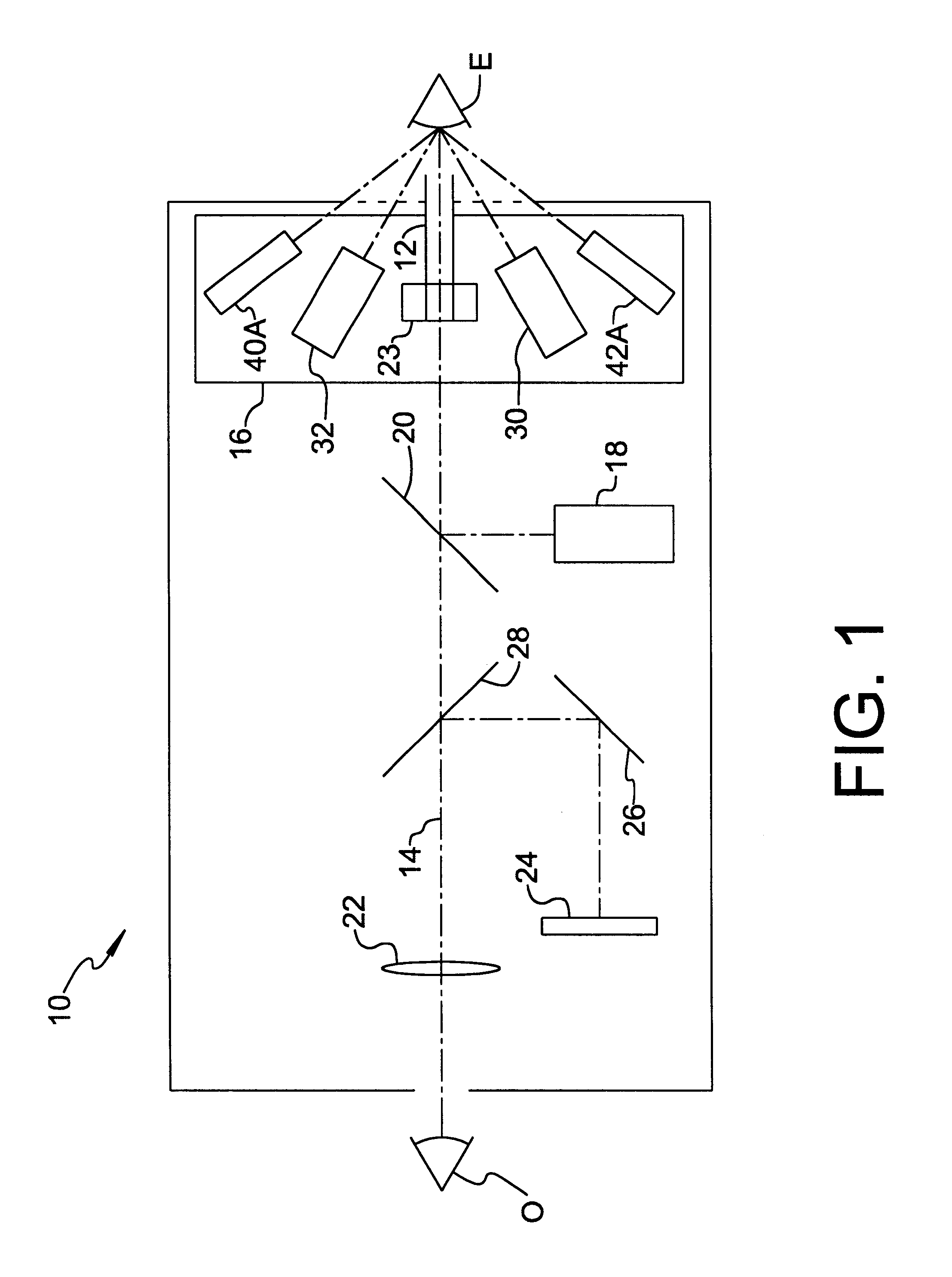
FIG. 1, an ophthalmic instrument incorporating a position detection system of the present invention is illustrated schematically and identified by the reference numeral 10. Instrument 10 is depicted as being a non-contact tonometer operable to discharge a fluid pulse through a fluid discharge tube 12 to cause observable deformation of a patent's cornea for purposes of measuring intraocular pressure. However, the present invention may be implemented in other types of ophthalmic instruments where it is necessary to ascertain the X-Y-Z alignment status of the instrument relative to an eye.

Instrument 10 includes an optical axis 14 along which discharge tube 12 is aligned, a nosepiece 16 fixed near a front portion of the instrument for mounting various optical and opto-electronic elements of the instrument as described below, a fixation target projecting system 18 cooperating with a beamsplitter 20 to present a visible fixation target to the patient along optical axis 14, an eyepiece 22 ...


PUM


Abstract

A fast position detection system and related method for an ophthalmic instrument utilize stored geometrical relationships determined by multiple regression during instrument calibration to compute X-Y-Z alignment status of the instrument relative to a patient's eye based on local x-y position information from a pair of lateral detectors receiving corneally reflected light from a corresponding pair of lateral light sources. In a preferred embodiment, the lateral detectors are quad-cell detectors. A heads-up display image is preferably provided along an optical axis of the instrument for supplying instructive cues to an operator for moving the instrument to achieve alignment, whereby the operator sees both a macro-image of the patient's eye and the display image. The speed of the position detection system makes it particularly suitable for use in hand-held ophthalmic instruments.

Description

I. Field of the InventionThe present invention relates generally to opto-electronic position detection systems for providing information regarding the three-dimensional alignment status of an ophthalmic instrument relative to an eye of a patient, and more particularly to an afocal position detection system capable of providing updated position information at a very high rate of repetition.II. Description of the Related ArtOpto-electronic position detection and alignment systems for use in locating an ophthalmic instrument relative to an eye to be tested are well known, as evidenced by U.S. Pat. No. 4,881,807 to Luce et al. Where the ophthalmic instrument is a non-contact tonometer having a discharge tube for directing a fluid pulse at the eye, X-Y alignment is typically achieved by aligning an axis of the discharge tube to intersect with the corneal vertex, and Z alignment is achieved by positioning a fluid exit end of the discharge tube at a predetermined distance from the corneal ...

Claims


Application Information

Patent Timeline
Patent Type & Authority Patents(United States)
IPC IPC(8): A61B3/113A61B3/12
CPCA61B3/113A61B3/1208A61B3/152
Inventor PERCIVAL, CHRISTOPHER J.HOOVER, DOUGLAS H.
Owner REICHERT
Why Eureka
Try Eureka