
Independent torsioning unit

Inactive Publication Date: 2004-06-22
GALAN INT
View PDF6 Cites 5 Cited by
  • Summary
  • Abstract
  • Description
  • Claims
  • Application Information

AI Technical Summary

Problems solved by technology

The productivity of the tandem formed by the spindles and the corresponding feeding rollers is limited by the feeding speed in relationship to the necessary torsioning degree for each work.

Method used


Image

  • Independent torsioning unit
  • Independent torsioning unit
  • Independent torsioning unit

Examples


Embodiment Construction

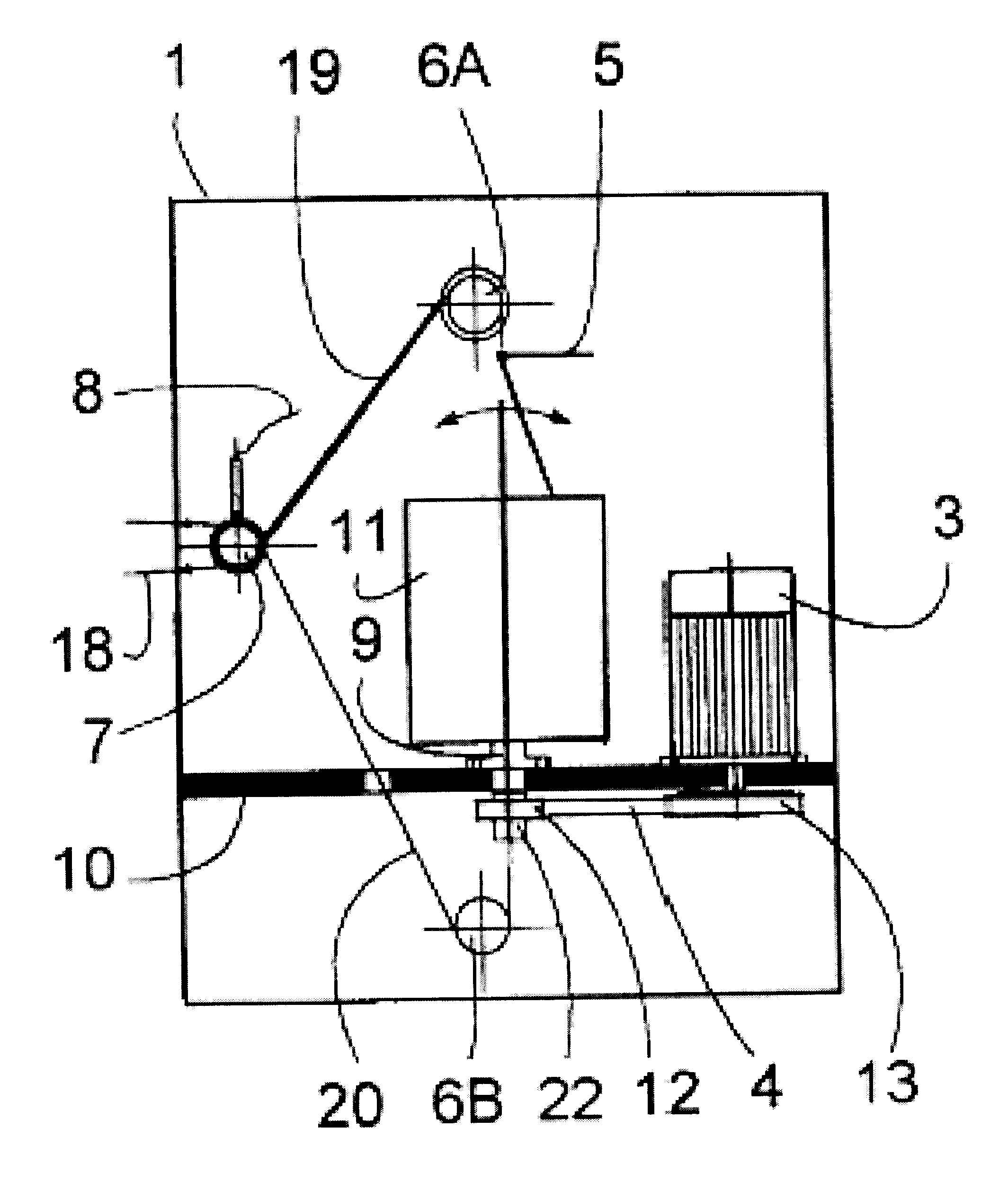
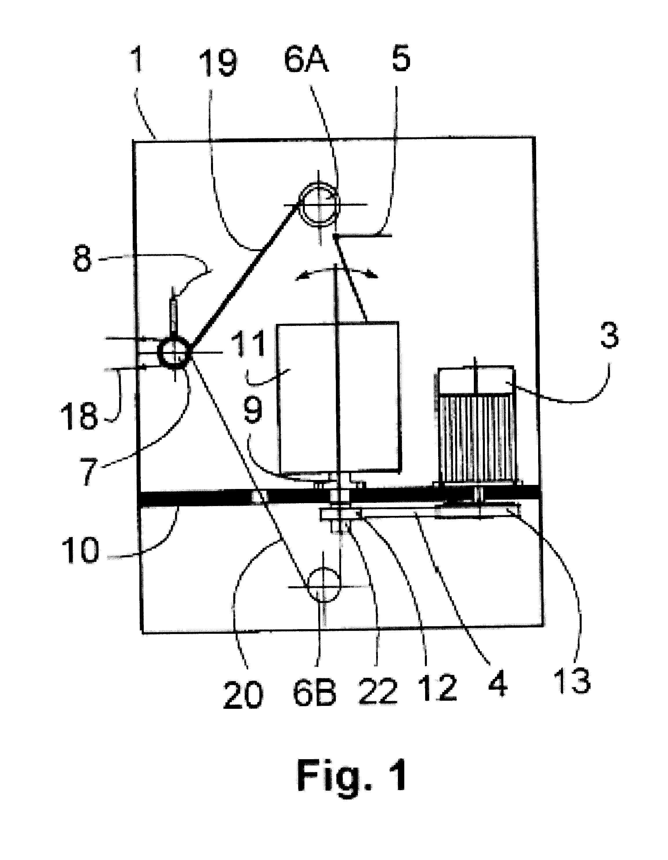
The independent torsioning unit is constituted by two clearly differentiated units: a case-frame and a programming and control unit. In the case-frame are housed a spindle and a reel, an electric motor, a drive belt, a yarn guide, a vertical deflection roller, a horizontal deflection sheave and a pulse reader. The spindle is a component that comprises several pieces, preferably vertical, that rotates on a support with a bearing that is fixed on the plate of the case-frame. The reel is introduced on said spindle with material that will be processed and the spindle is endowed with orientation capacity comprised between 0.degree. and 45.degree. (for the spindle types requiring it). At the bottom of said spindle it is attached a pulley that is moved, through a flat, preferably geared belt, by the electric motor pulley.

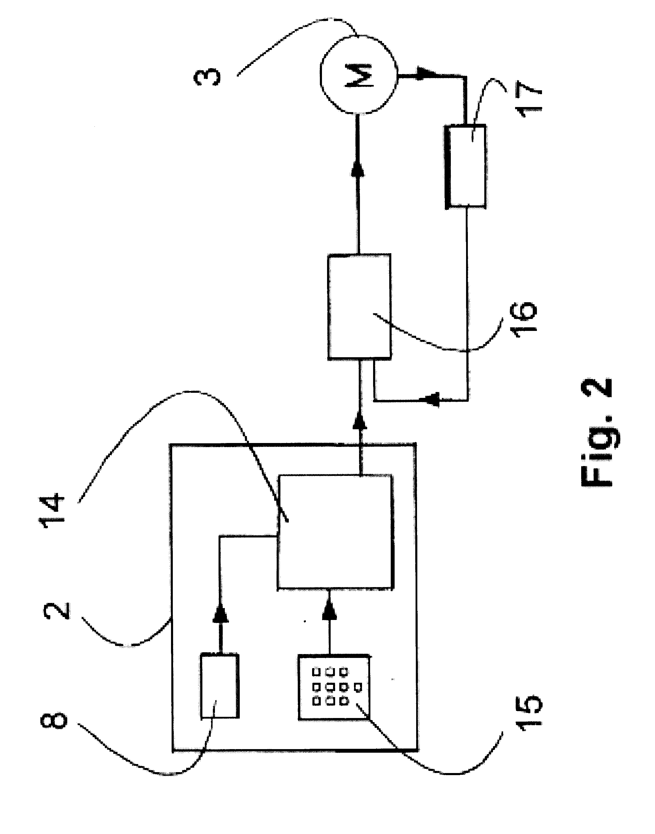
The programming and control unit comprises a processor, a programming keyboard and a frequency converter, which supplies and manages the motor. The thread to be processed ...


PUM


Abstract

The independent torsioning unit consists of two different units: the case frame and the programming and control unit. The case frame houses the spindle axis, the electrical motor, the drive belt, the yarn guide, the vertical deflection roller, the horizontal deflection pulley and the impulse reader. The programming and control unit consists of a processor, the programming keyboard and a frequency converter that supplies and controls the motor. The independent torsioning unit is used as an auxiliary feeding machine that enhances the performance of any type of main processing machine.

Description

OBJECT OF THE INVENTIONThe object of the present invention refers, as its title indicates, to an independent torsioning unit used, through this torsioning unit, to feed spinning, twisting and other operating machines, in the textile industry, with materials derived from glass, polyamide, technical threads and other products.A series of machines are used in the textile industry with the purpose of making yarn, twisting threads, manufacturing cords and other similar operations, that are fed from several static reels by proper means of said machines. These means are feeding rollers that are synchronised with the spindles of said machines in order to provide the desired torsioning degree to the carried out work.The productivity of the tandem formed by the spindles and the corresponding feeding rollers is limited by the feeding speed in relationship to the necessary torsioning degree for each work.DESCRIPTION OF THE INVENTIONThe independent torsioning unit is constituted by two clearly d...

Claims


Application Information

Patent Timeline
IPC IPC(8): B65H59/00B65H59/38D01H1/16D01H1/00D01H1/244
CPCB65H59/384D01H1/16D01H1/244B65H2701/31
Inventor LLONGUERAS, JORDI GALAN I
Owner GALAN INT
Learn More