Syringe needle cover

a protection cover and needle technology, applied in the field of syringe needle protection covers, can solve the problems of unprotected needles, accidental puncture of protection covers, and bystanders, such as medical staff, to be lost or bystanders, to be accidentally punctured, etc., and achieve the effect of less likely to be reopened

Inactive Publication Date: 2004-06-22
TUEN YU YING
View PDF7 Cites 20 Cited by
  • Summary
  • Abstract
  • Description
  • Claims
  • Application Information

AI Technical Summary

Benefits of technology

Another object of the invention is to have a needle cover that gives users more than one visual indication that a needle has been used, thereby reducing the likelihood that a needle will be reused.
The fourth locking structure is also non-releasable. Within the Axial Slot of the Longitudinal Member, there is at least one pair of Locking Bars that extend diagonally from the inside surface of the Longitudinal Member, and that, when viewing the Longitudinal Member along its long axis, form intersections. When the Longitudinal Member is resheathed after use, the needle goes through the Locking Bars and enters the space between the Locking Bars and the inside surface of the Longitudinal Member, so that even if the Longitudinal Member is forcibly reopened, the needle inside is deformed when going through the intersecting Locking Bars. This further reduces the possibility that the needle will be reused.
Another feature of the invention is that the needle cover deforms the needle to prevent reuse.
The advantages of having multiple locking structures include the following. With multiple locking structures, the Longitudinal Member is less likely to be reopened after use, thereby making it less likely that a needle will be reused. Multiple locking structures also make the entire Protection Cover stronger and less likely to be reopened.
The advantages of having visual indications of needle use include the following. Before the needle is used, the Longitudinal Member closes in an erect position relative to the Needle Hub. After the needle is used, the Longitudinal Member closes in a diagonal position relative to the Needle Hub. The diagonal position provides a visual indication that the needle is used. Additionally, the fourth locking structure discussed above deforms the needle (either upon initial closing of the Longitudinal Member, subsequent reopening, or both), which provides an additional indication that the needle has been used. The multiple visual indications of needle use make it less likely that a needle will be reused.

Problems solved by technology

As such, it is possible for the protection cover to be lost or for bystanders, such as members of the medical staff, to be accidentally punctured by the uncovered needle.
The unprotected needle creates disposal problems.
Protection covers, however, can get lost, and, as such, syringe needles are sometimes discarded without any protection covers or without properly attached protection covers.
However, a problem arises because the protection cover can be reopened after enclosing the needle.
If a used needle is not properly discarded, it may not be possible for members of the medical staff to recall whether or not the needle has been used, which could lead to the reuse of a needle.
Even worse, different medicines could be inadvertently mixed in the syringe, which may cause sanitation problems, patient injury, or death.
While Sponsel discloses a bendably attached slotted protective needle cover, the '451 needle guard does not give any indication whether or not a needle has been used.
However, for disposable syringe needles, the needle should not be reused, and it is desirable to have the needle damaged to prevent reuse of the needle.
While Hollister discloses a bendably attached slotted protective needle cover, the '455 protective housing does not give the user visual indications that the needle has been used.
None of the above prior art discusses syringe needle protection covers that give users more than one visual indication that a needle has been used.
This further reduces the possibility that the needle will be reused.
The needle is deformed, bent, or otherwise damaged as a result of the operation of the fourth locking structure.
Even if the Longitudinal Member is forcibly reopened after having been closed, the Locking Bars sufficiently damage the needle to prevent its reuse.

Method used


Image

  • Syringe needle cover
  • Syringe needle cover
  • Syringe needle cover

Examples


Embodiment Construction

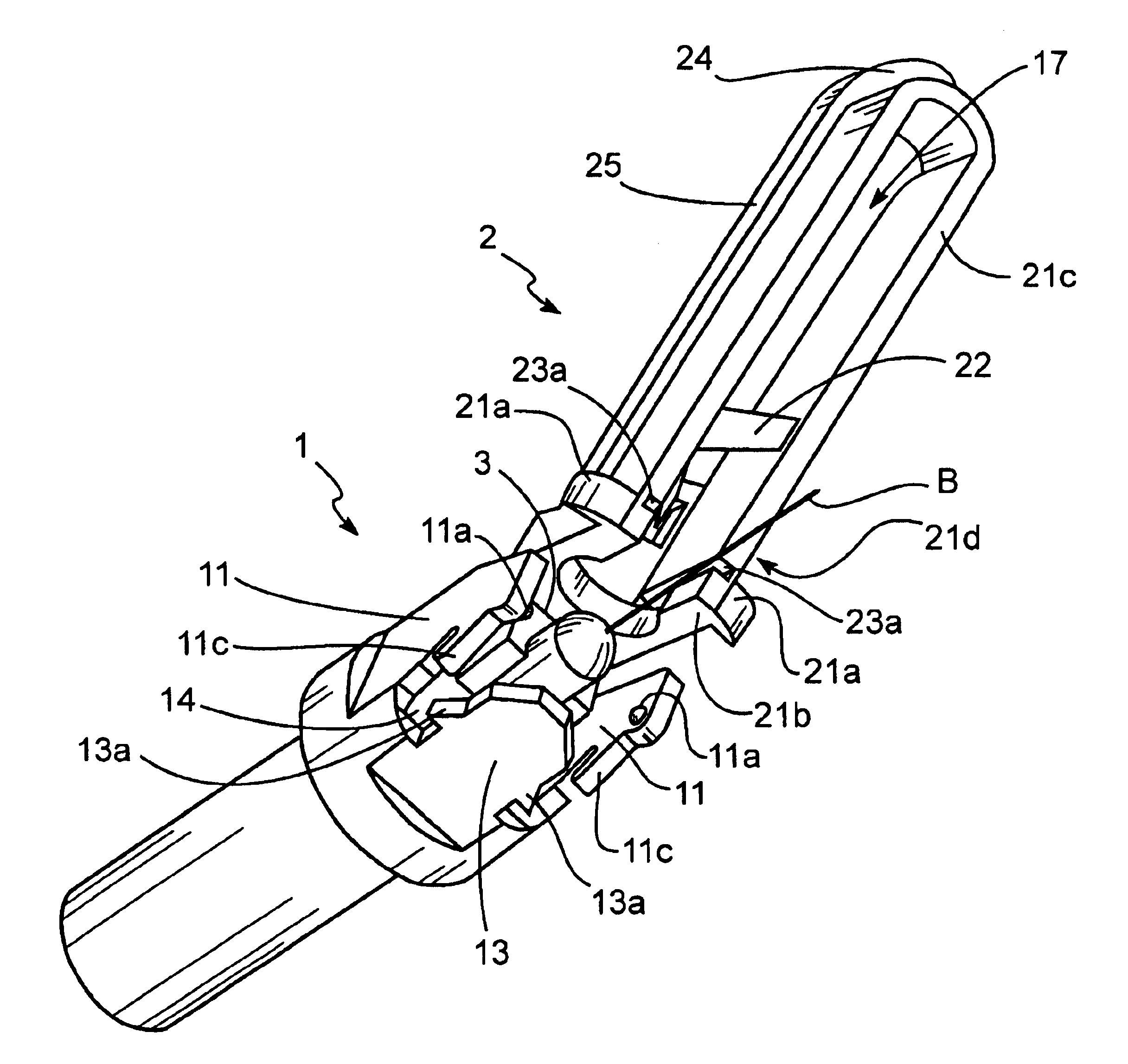
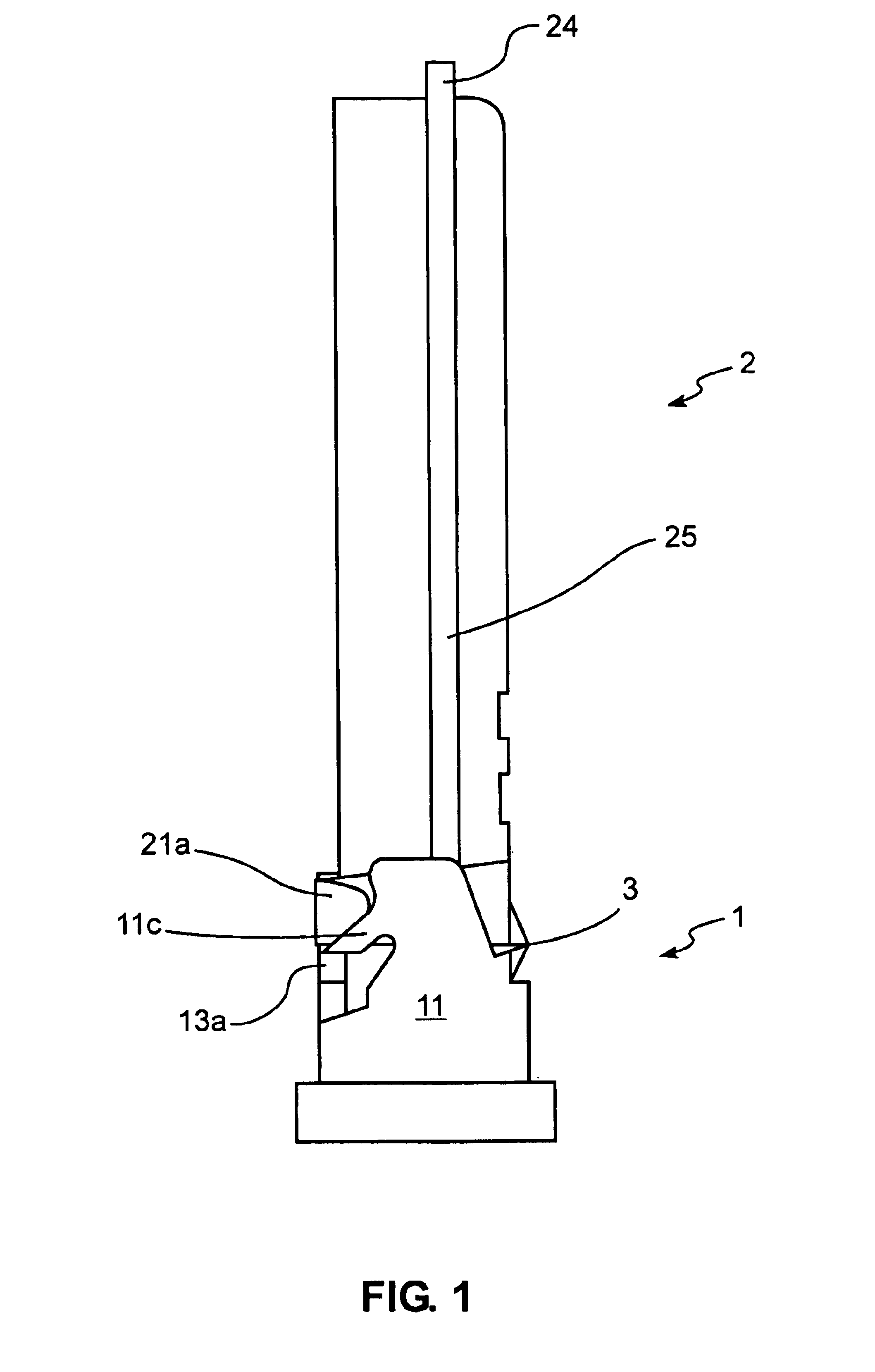
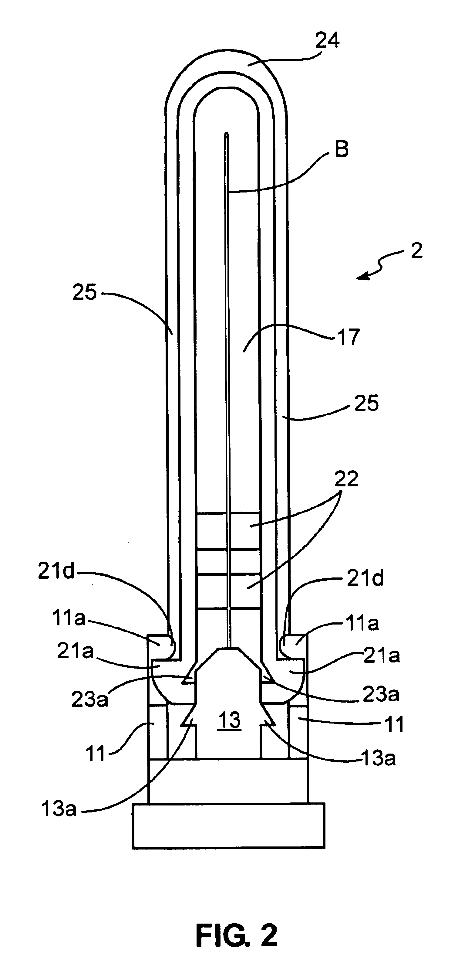
The following is a detailed description of the Protection Cover according to the invention with reference to FIGS. 1-7.

As indicated in FIG. 1 and FIG. 2, the Protection Cover includes a Needle Hub 1 and a Longitudinal Member 2. The Needle Hub 1 is used to secure the base of a syringe needle (not indicated), and the Longitudinal Member 2 is used to cover and protect a needle such as a Cannula Needle B. Typically, the Cannula Needle B is at the center of the needle base (not indicated). The Protection Cover has a Hinge 3, which integrates with the Longitudinal Member 2 at the back side of the Needle Hub 1. U-shaped Brim 21b has two Locking Protrusions 21a at the lower part of the Longitudinal Member 2 (see FIG. 4). There are Side Blocks 11 at the two sides of the Needle Hub 1 and on top of the Side Blocks 11 are Locking Protrusions 11a corresponding to and that interlock with Detents 21d on the outside of the Longitudinal Member 2. The Locking Protrusions 11a are optimized to be knob-...


PUM


Abstract

The invention is a syringe needle Protection Cover, including a Needle Hub to secure the needle base and a side-opening cover with an Axial Slot to protect the needle. The needle is at the center of the needle base, and a Longitudinal Member forms a side-opening cover that integrates with the Needle Hub at one side via a Hinge. The Longitudinal Member opens easily and locks closed securely. When the Protection Cover is in the closed position, it is difficult to force open, thus making it difficult to reuse a needle. The protection cover gives users more than one visual indication that a needle has been used, locks in a closed position with multiple locking structures, and after use, deforms the needle so as to render it non-reusable.

Description

Applicant claims priority of Chinese application in the name of TUEN, Yu Ying, filing number 01231198.7, filed Jul. 7, 2001, issued Mar. 1, 2002.1. Field of the InventionThe invention relates to protection covers for syringe-type needles, including syringe needles used for medical treatment, dentistry, veterinary treatment, and laboratory work, and including needles such as subcutaneous syringe needles, intravenous syringe needles, LUER-LOK type syringe needles, and hemospasia syringe needles.2. Description of Prior ArtMany pathogens are known to be transmitted by needle-stick injuries. As such, the prior art includes a large number of needle packaging structures designed to prevent such injuries. Injection molding processes allow for the manufacture of single-piece disposable needle packaging structures. Disposable syringe needles generally include a needle, a syringe, and a protection cover. For disposable syringe needles commonly used in hospitals or other medical institutions, t...

Claims


Application Information

Patent Timeline
Patent Type & Authority Patents(United States)
IPC IPC(8): A61M5/32
CPCA61M5/3216A61M5/5086A61M2205/583
Inventor TUEN, YU YING
Owner TUEN YU YING
Why Eureka
Try Eureka