Superconducting cable

Inactive Publication Date: 2004-07-06
PRYSMIAN CAVI E SISTEMI ENERGIA +1
View PDF9 Cites 17 Cited by
  • Summary
  • Abstract
  • Description
  • Claims
  • Application Information

AI Technical Summary

Benefits of technology

It has now been found that by partially filling the gaps among the tapes of superconductin

Problems solved by technology

The Applicant has found that high gaps among tapes of superconducting material may produce damages to the tapes due to the pressure exerted on the tapes by the parts surrounding them and t

Method used


Image

  • Superconducting cable
  • Superconducting cable
  • Superconducting cable

Examples


example 1

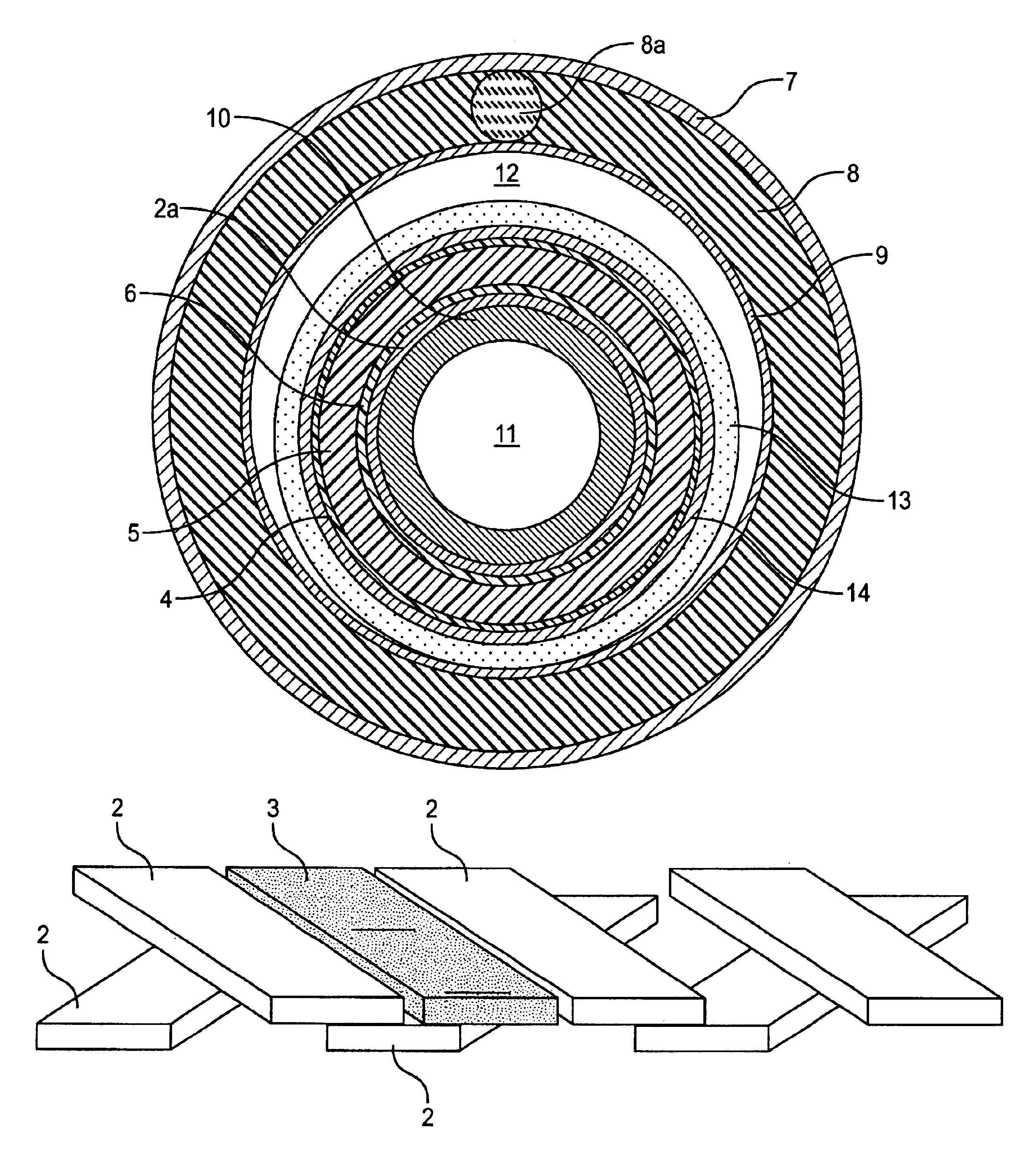
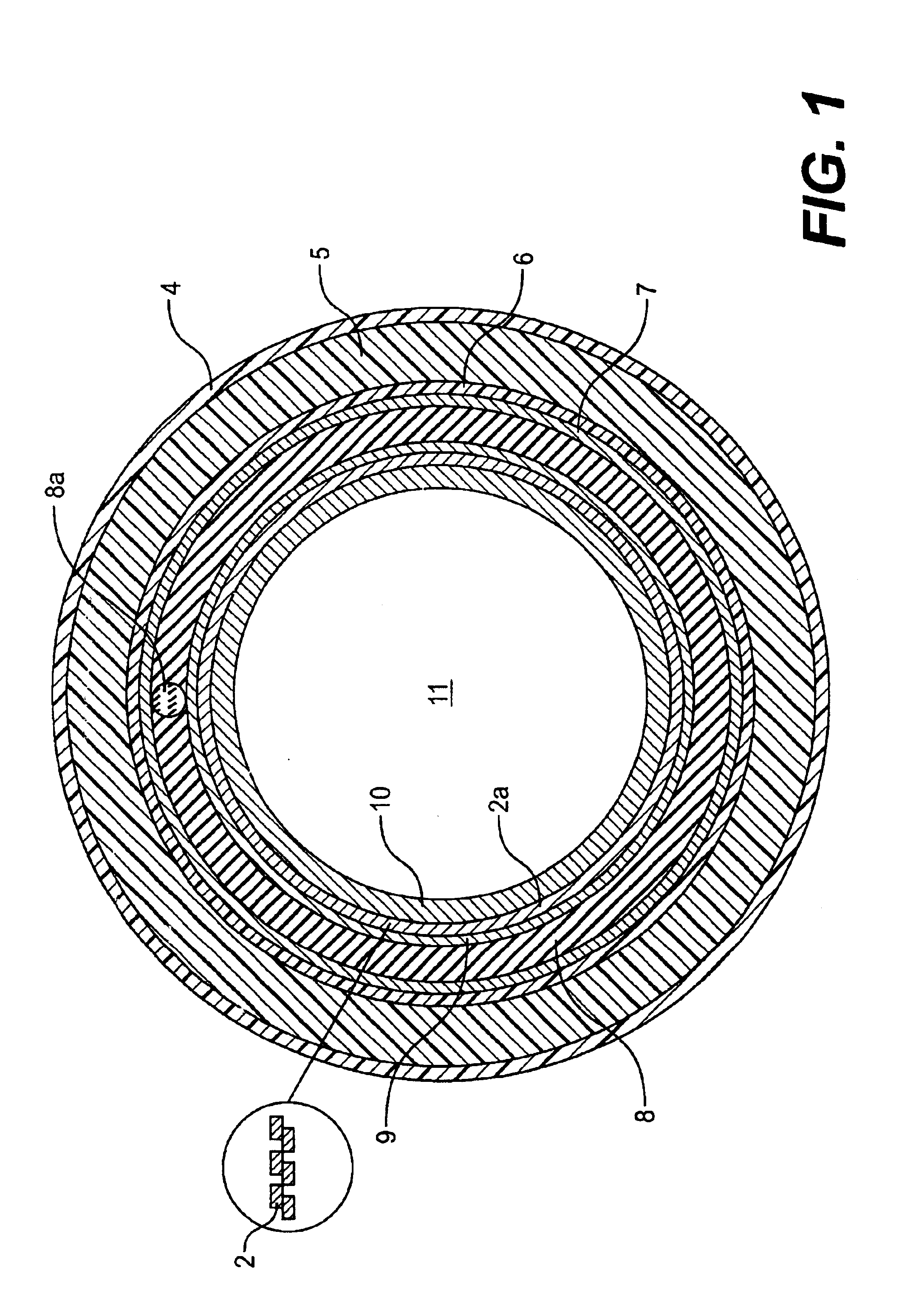
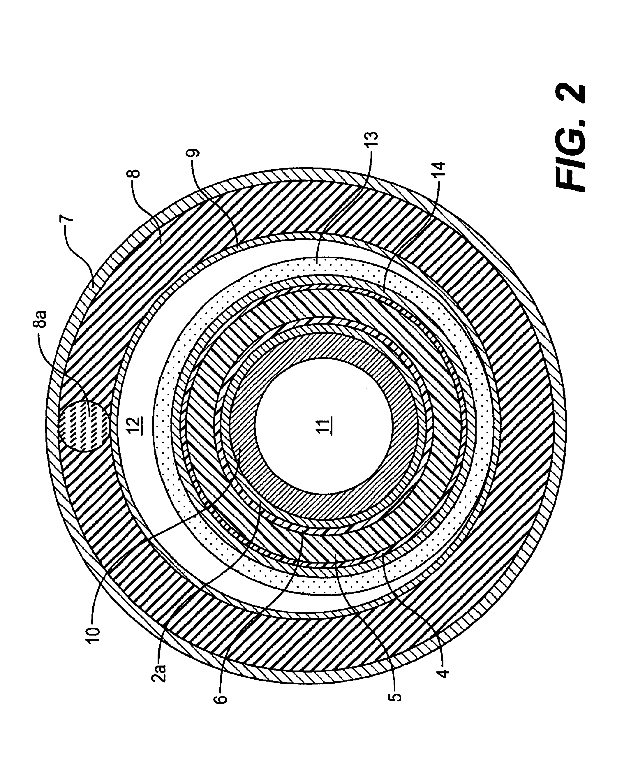
Two cold dielectric superconducting cables, 15 m long respectively, were made by assembling:

a tubular former

a phase conductor consisting of 2 layers of tapes of superconducting material helicoidally wound with opposite direction each other

a lapped dielectric

a return conductor consisting of 2 layers of tapes of superconducting material helicoidally wound with opposite direction each other

The tapes of superconducting material employed were 4.1 mm wide and 0.3 mm thick.

The phase conductor was made by winding two layers of 24 tapes each on a tubular former having an external diameter of 46 mm. The tapes were helicoidally wound with an angle of, respectively, about 30.degree. and about -30.degree.. The gap between two tapes was of about 0.8 mm.

The return conductor was made by winding 2 layers of 24 tapes each on the dielectric insulator having an external diameter of 85.20 mm.

In the cable according to the prior art (cable 1) the tapes of superconducting material of the return conductor w...


PUM

PropertyMeasurementUnit
Fractionaaaaaaaaaa
Widthaaaaaaaaaa
Widthaaaaaaaaaa

Abstract

A superconducting cable includes at least one layer of tapes of superconducting material circumferentially wound side by side on a support at a prefixed distance forming gaps circumferentially among adjacent tapes. Within the superconducting cable, a non-superconducting material is interposed between adjacent tapes to partially fill the gaps.

Description

The present invention relates, in its more general aspect, to a superconducting cable having at least one superconducting layer.The term "superconducting cable" indicates an electrical transmission cable comprising at least an element of superconducting material.The superconducting cable of the present invention may be a warm dielectric (WD) or cold dielectric (CD) cable. See, for example, Engelhardt J. S. et al., Application Consideration for HTSC Power Transmission Cable, 5.sup.th Annual Conference on Superconductivity and Application, Buffalo, N.Y., Sep. 24-26, 1991, FIG. 5 for a WD cable, and FIG. 6 for a CD cable.A WD cable generally comprises one or more layers of tapes of superconducting material wound on a support, typically tubular, defining the cryogen fluid flow channel. Externally to the superconducting tapes a cryostat and an electric insulator are provided.A CD cable generally comprises, in addition to the layers mentioned above for the WD cable, further layer(s) const...

Claims


Application Information

Patent Timeline
IPC IPC(8): H01B12/02H01B12/06
CPCH01B12/02H01B12/06Y10T29/49014Y02E40/641Y02E40/642Y02E40/60
Inventor SPREAFICO, SERGIO
Owner PRYSMIAN CAVI E SISTEMI ENERGIA
Why Eureka
Try Eureka