Motor driving apparatus and control method thereof

a motor and motor technology, applied in the direction of dynamo-electric converter control, pulse technique, stopping arrangement, etc., can solve the problems of increasing the current flowing through the coil increasing the number of rotations of the motor, deteriorating the mechanical reliability of the apparatus, etc., to avoid any mechanical damage to the motor, without increasing the circuit size

Inactive Publication Date: 2012-07-10
RENESAS ELECTRONICS CORP
View PDF22 Cites 19 Cited by
  • Summary
  • Abstract
  • Description
  • Claims
  • Application Information

AI Technical Summary

Benefits of technology

[0014]In the motor driving apparatus 1B disclosed in Japanese Unexamined Patent Application Publication No. 02-290174, the power supply voltage supplied to the motor drive circuit 3B rises due to the back electromotive force generated by the motor 4B coming into the regenerative state. Thus, when the detection circuit 5B detects an abnormality of the power supply voltage supplied to the motor drive circuit 3B, the bias circuit 5B causes the FET 7B to turn on to thereby short circuit the coils of the motor 4B. This allows the motor 4B to provide regenerative (power generation) breaking, and also allows the motor 4B itself to eliminate the back electromotive force. In this method, however, the motor 4B is rapidly stopped, and a mechanical load is applied to the motor itself. This leads to a deterioration in the mechanical reliability of the apparatus, and an increase in the risk of causing a failure. Moreover, a control circuit such as a bias circuit is required, which causes a problem of an increase in circuit size.
[0018]According to an exemplary embodiment of the present invention, the back electromotive force can be absorbed to thereby avoid any mechanical damage to a motor, without increasing the circuit size.

Problems solved by technology

When the pulse width is large, the transistor is turned on for a long time, which leads to an increase in the current flowing through the coils of the motor and an increase in the number of rotations of the motor.
In this case, in the inverter control for the brushless DC motor, if the driving of the motor cannot be controlled due to rapid deceleration of the motor, a system malfunction, or the like, the motor comes into a regenerative (power generation) state owing to load inertia, resulting in generation of a large back electromotive force.
This leads to a deterioration in the mechanical reliability of the apparatus, and an increase in the risk of causing a failure.
Moreover, a control circuit such as a bias circuit is required, which causes a problem of an increase in circuit size.

Method used


Image

  • Motor driving apparatus and control method thereof
  • Motor driving apparatus and control method thereof
  • Motor driving apparatus and control method thereof

Examples


Embodiment Construction

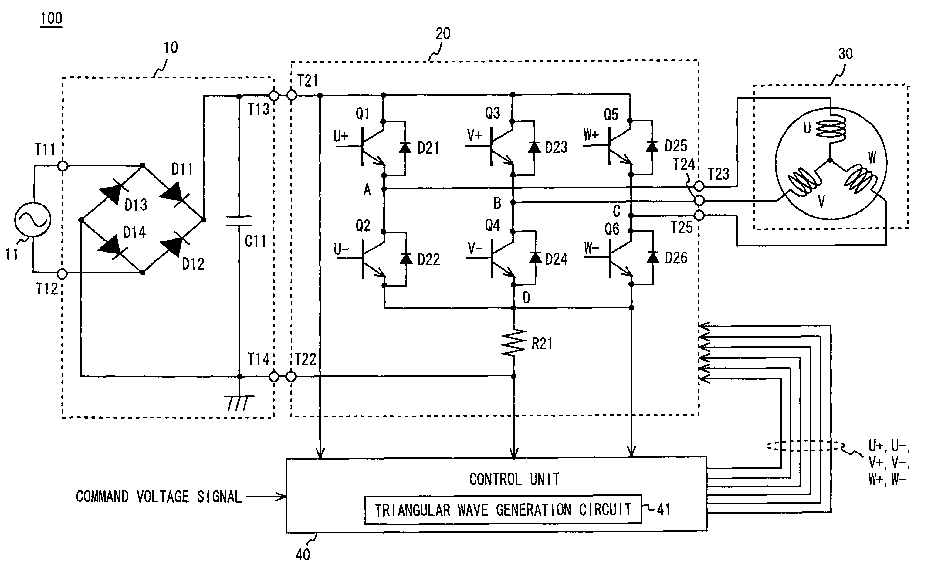
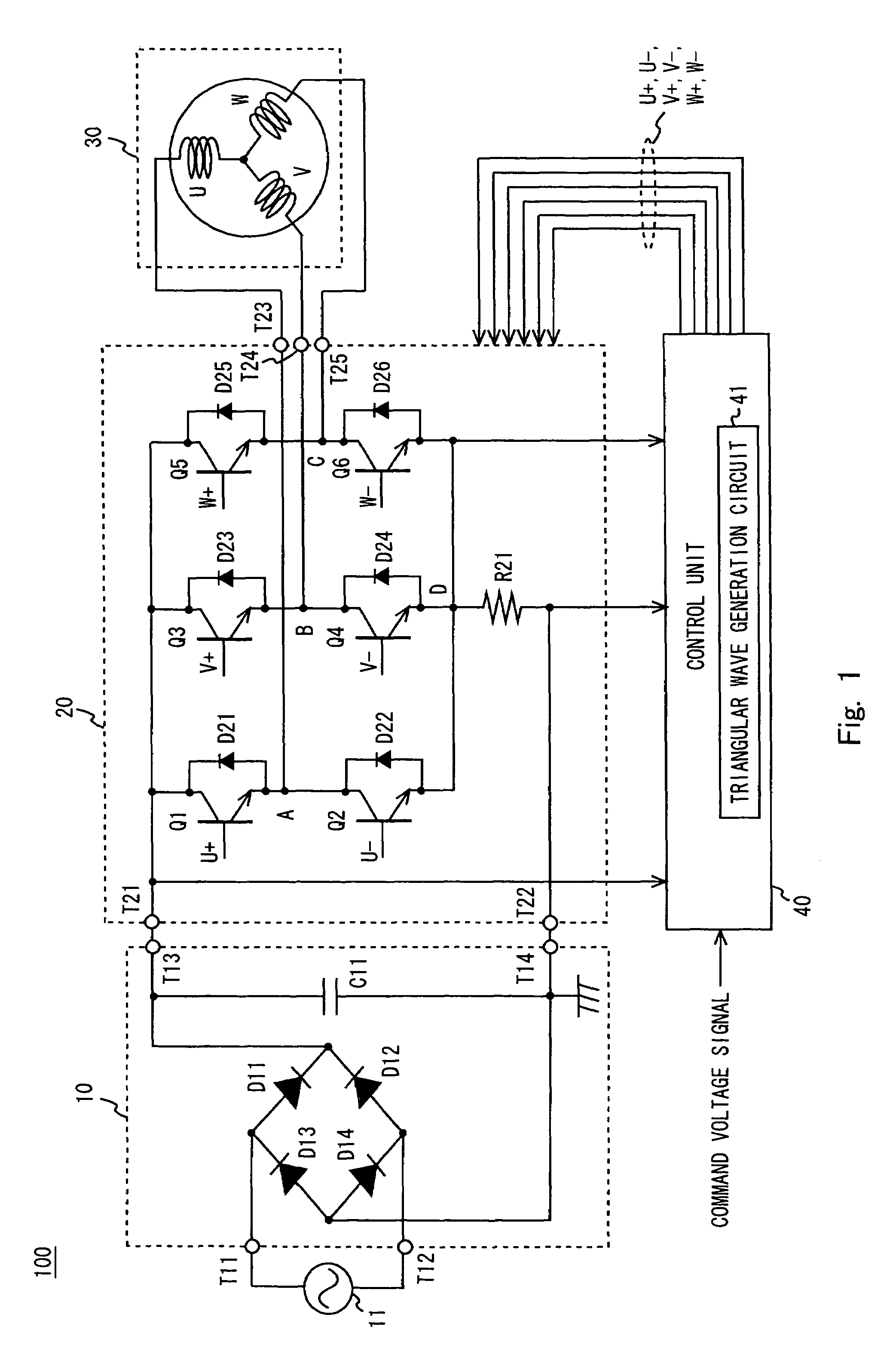
[0029]Exemplary embodiments to which the present invention is applied will be described in detail below with reference to the drawings. In this exemplary embodiment, the present invention is applied to a motor driving apparatus. FIG. 1 shows an example of the configuration of a motor driving apparatus 100 according to this exemplary embodiment. As shown in FIG. 1, the motor driving apparatus 100 includes a converter unit 10, an inverter unit 20, a brushless DC motor 30, and a control unit 40.

[0030]The converter unit 10 rectifies a voltage supplied from a general commercial AC power supply 11 to convert it into a DC voltage. The converter unit 10 includes input terminals T11 and T12, output terminals T13 and T14, rectifier diodes D11 to D14, and a smoothing capacitor C11. The rectifier diode D11 has an anode connected to the input terminal T11 and a cathode connected to the output terminal T13. The rectifier diode D12 has an anode connected to the input terminal T12 and a cathode con...


PUM


Abstract

Provided is a motor driving apparatus including a motor drive unit including a plurality of transistors which are repeatedly turned on and off in response to a pulse having a pulse width modulated at a first carrier frequency to control driving of a motor in a normal operation state and which supply a drive current to the motor; and a control unit that controls the plurality of transistors to be turned on and off in response to a pulse having a pulse width modulated at a second carrier frequency higher than the first carrier frequency, when a voltage applied between input terminals of the motor drive unit rises to a predetermined value.

Description

BACKGROUND[0001]1. Field of the Invention[0002]The present invention relates to a motor driving apparatus and a control method thereof, and more particularly, to a brushless DC motor.[0003]2. Description of Related Art[0004]Permanent magnet synchronous motors having a small size and a high output are now widely employed in the field of consumer products such as washing machines, refrigerators, and air conditioners which are required to be downsized.[0005]Recent technological innovations in the field of power devices such as MOS-FETs make it possible to realize an inverter control in which a commercial AC power supply is temporarily rectified and converted into a DC power supply and is then regenerated into a given drive waveform through a switching operation of a power device. The inverter control facilitates power saving and control operation. Further, brushless DC motors for driving the permanent magnet synchronous motor as described above are now widely used.[0006]FIG. 6 shows an...

Claims


Application Information

Patent Timeline
Patent Type & Authority Patents(United States)
IPC IPC(8): H03K5/00H02P6/06H02P6/08H02P6/24H02P6/28
CPCH02P6/182H02P6/24H02P29/022H03K7/08H02P2205/01H02P29/032
Inventor IKEI, SATOSHI
Owner RENESAS ELECTRONICS CORP
Why Eureka
Try Eureka