Method, system, and apparatus for operating a sucker rod pump

a sucker rod pump and pump body technology, applied in the direction of pump parameters, positive displacement liquid engines, instruments, etc., can solve the problems of high power requirements of sucker rod pumps, high maintenance costs, and high repair labor and parts costs, so as to achieve the effect of reducing calibration and operator intervention, and convenient installation and operation

a sucker rod pump and pump body technology, applied in the direction of pump parameters, positive displacement liquid engines, instruments, etc., can solve the problems of high power requirements of sucker rod pumps, high maintenance costs, and high repair labor and parts costs, so as to achieve the effect of reducing calibration and operator intervention, and convenient installation and operation

US20090311107A1Active Publication Date: 2009-12-17GASOLINEOG AUTOMATION

Image

  • Method, system, and apparatus for operating a sucker rod pump
  • Method, system, and apparatus for operating a sucker rod pump
  • Method, system, and apparatus for operating a sucker rod pump

Examples


Embodiment Construction

[0033]Certain exemplary but non-limiting embodiments of the present invention are now described with reference to the attached drawings.

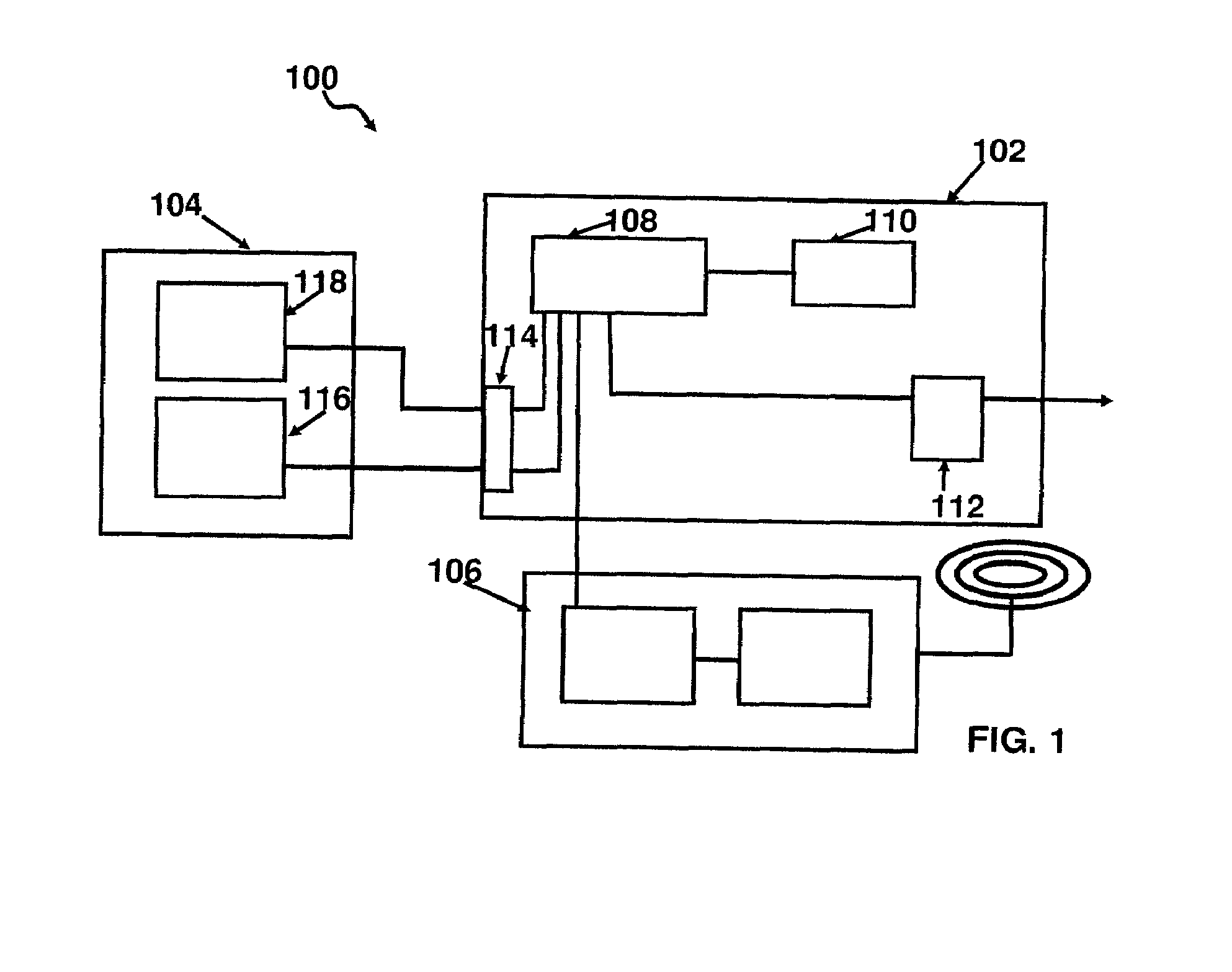
[0034]Referring now to FIG. 1, there is shown a schematic representation of an apparatus 100 according to the present invention, including microcontroller module 102, sensor module 104, and wireless module 106.

[0035]Microcontroller module 102 comprises a microcontroller 108 and non-volatile memory 110 in electronic communication. Microcontroller 108 is further in electronic communication with one or more actuators 112, such as for example high current relays, for controlling operation of the prime mover of the pump, and with a plurality of ports 114 for collecting sensor inputs and for communicating with wireless module 106. Preferably, microcontroller input and output ports are optically isolated.

[0036]As used herein, the term “microcontroller” refers without limitation to any microprocessor design that preferably emphasizes high integration, low p...


PUM


Abstract

Apparatus, methods, and system for wireless remote monitoring and controlling a sucker rod pump for producing hydrocarbons, providing self-adjusting methods for operation over a wide-range of operating conditions according to algorithms that automatically compensate for offset and amplitude drift in sensor data, automatically identify pump off conditions, and automatically optimize hold down time.

Description

FIELD OF THE INVENTION[0001]The present invention relates to an apparatus, system and method for the monitoring and control of sucker rod pumps for the production of hydrocarbons. More particularly, the present invention relates to an apparatus, system and method for monitoring and analyzing pump conditions in real time, for controlling operation of the pump, and for remote monitoring and control.BACKGROUND OF THE INVENTION[0002]Hydrocarbons are often produced from well bores by sucker rod pumps, which are reciprocating pumps driven from the surface by drive units that move a polished rod up and down through a packing gland at a wellhead. Typically, a walking beam is pivotally mounted with one end of the beam being attached to the rod and with the beam being reciprocated by a drive unit. The drive unit consists of a prime mover connected to a reduction unit that drives a crank to reciprocate the walking beam.[0003]While sucker rod pumps are relatively simple units, they are expensiv...

Claims


Application Information

Patent Timeline
17 Dec 2009
Publication
US20090311107A1
IPC
F04B49/00
CPC
F04B47/02; F04B2201/121; F04B2201/0201
Inventors
CHAVEZ ZAPATA, CESAR ANTONIO