Wine rack and kit and method for its onsite assembly

a wine rack and kit technology, applied in the field of wine racks, can solve the problems of high cost per bottle capacity of such cabinets, large amount of bottles which can be stored, and design to be aesthetically pleasing, and achieve the effects of rapid, accurate and economical assembly onsite, easy to manufacture offsite, and convenient assembly offsi

Inactive Publication Date: 2004-07-20
WOODS DANIEL
View PDF33 Cites 75 Cited by
  • Summary
  • Abstract
  • Description
  • Claims
  • Application Information

AI Technical Summary

Benefits of technology

It is an object of this invention to provide a wine rack on which a plurality of wine bottles of a standard volume which have slightly varying diameters can be compactly stored without their sidewalls touching. It is another object to provide a wine rack which is aesthetically pleasing, both when empty and when partially or completely filled with bottles stored thereon. It is another object to provide the structural elements of a wine rack which can be readily, economically and expeditiously fabricated offsite and which can be assembled inexpensively and rapidly onsite and, in its preferred embodiments manually without tools by unskilled individuals. It is a further object to provide a conveniently transportable kit comprising the unassembled but completely fabricated structural elements of a wine rack which can rapidly, accurately and economically be assembled onsite. Another object is to provide an economical method-of rapidly and economically fabricating offsite the critical structural elements of a wine rack. Other objects will be apparent to those skilled in the art to which this invention pertains.

Problems solved by technology

The cost per bottle capacity of such cabinets makes storage of a large number of wine bottles, e.g., in the order of several hundred or thousand, is very high.
The former are limited in the amount of bottles which can be stored therein and the latter, although functionally adequate, are intended for a storage area such as a wine cellar and are not designed to be aesthetically pleasing.
The prior art also lacks a method of fabricating offsite and assembled onsite a wine rack whose size presents transportation and / or installation issues when it is both fabricated and assembled offsite and labor costs and quality control when it is both fabricated and assembled onsite.
There also is lacking in the prior art a kit containing the structural elements of a wine rack which can be fabricated accurately, economically and rapidly offsite, which can easily be transported to an installation site and which can be accurately, economically and rapidly assembled onsite into a wine rack and installed thereat by unskilled labor without onsite fabrication of a structural element thereof

Method used


Image

  • Wine rack and kit and method for its onsite assembly
  • Wine rack and kit and method for its onsite assembly
  • Wine rack and kit and method for its onsite assembly

Examples


example 1

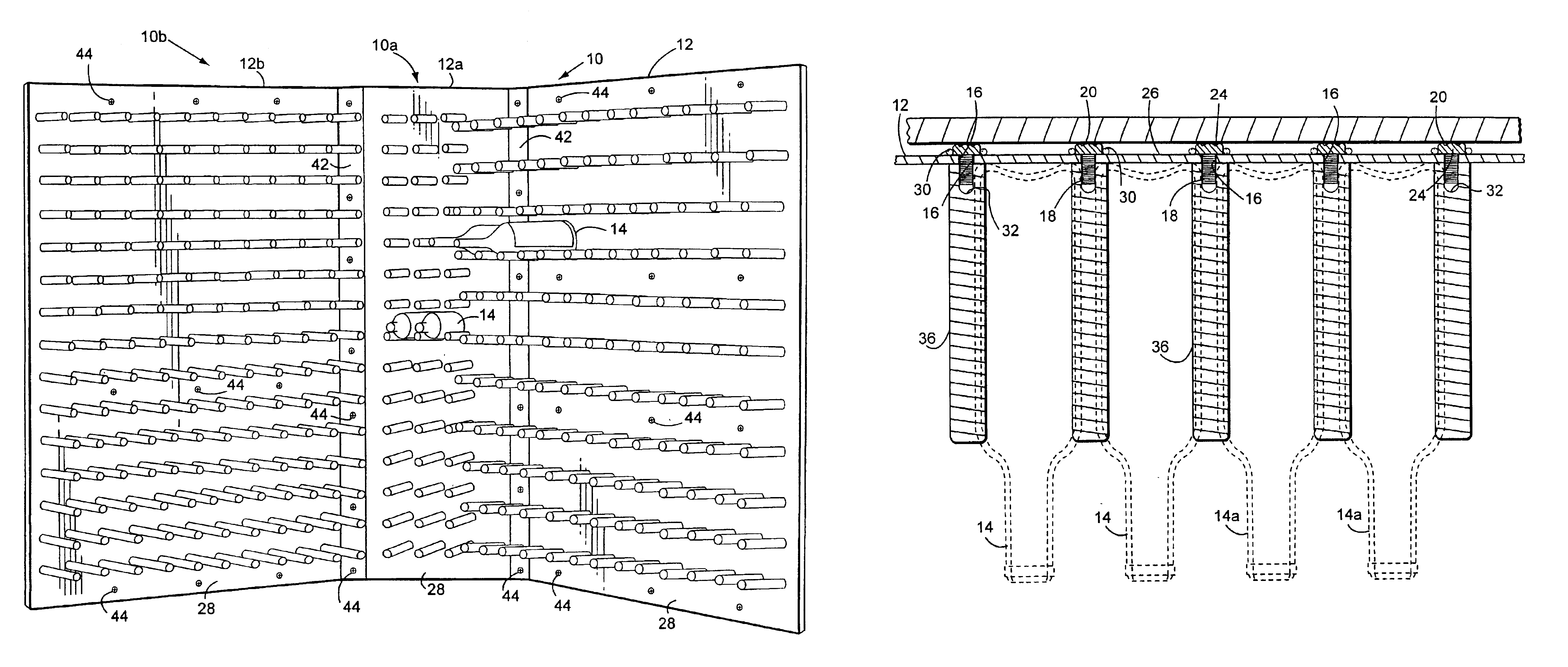
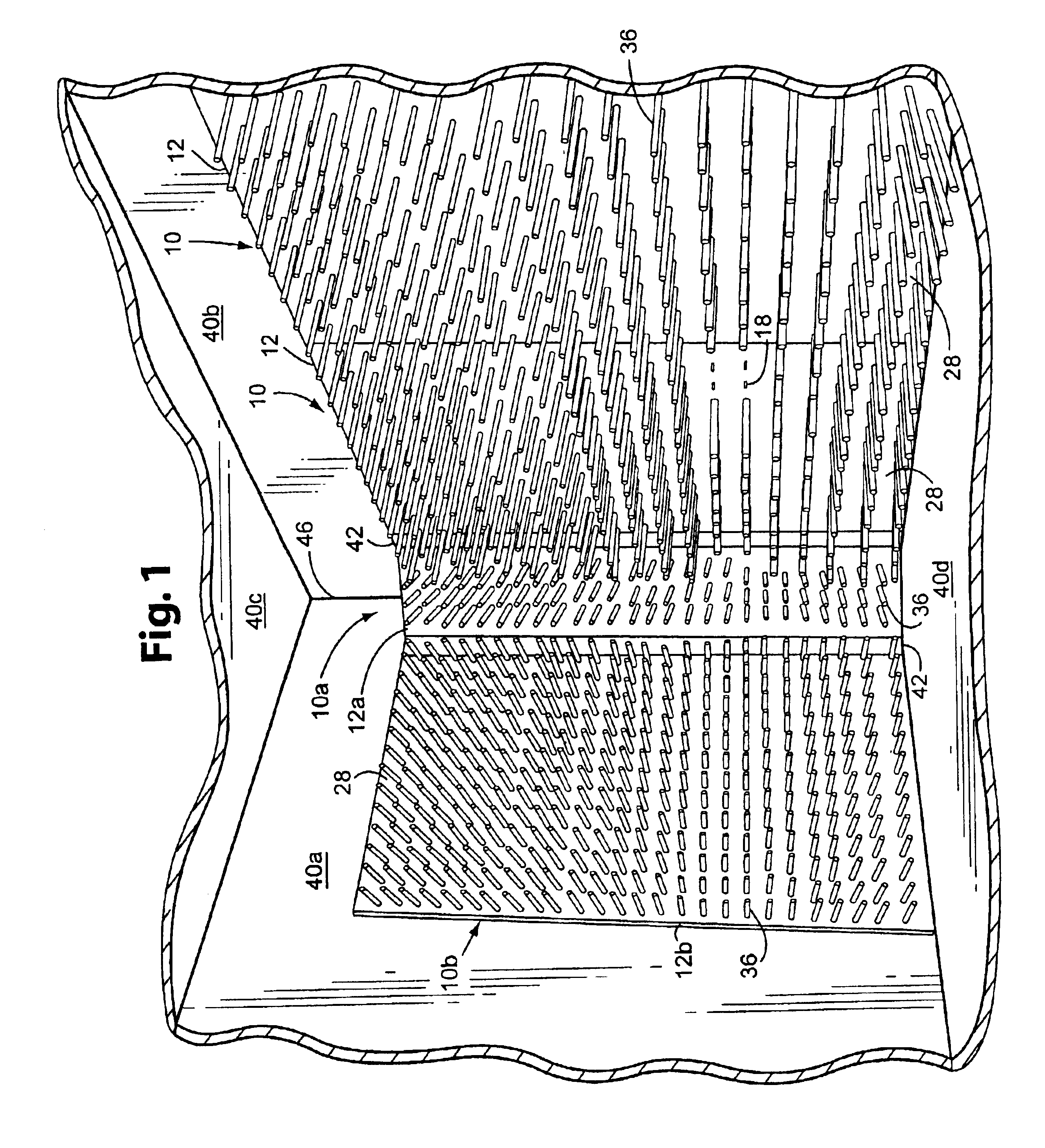
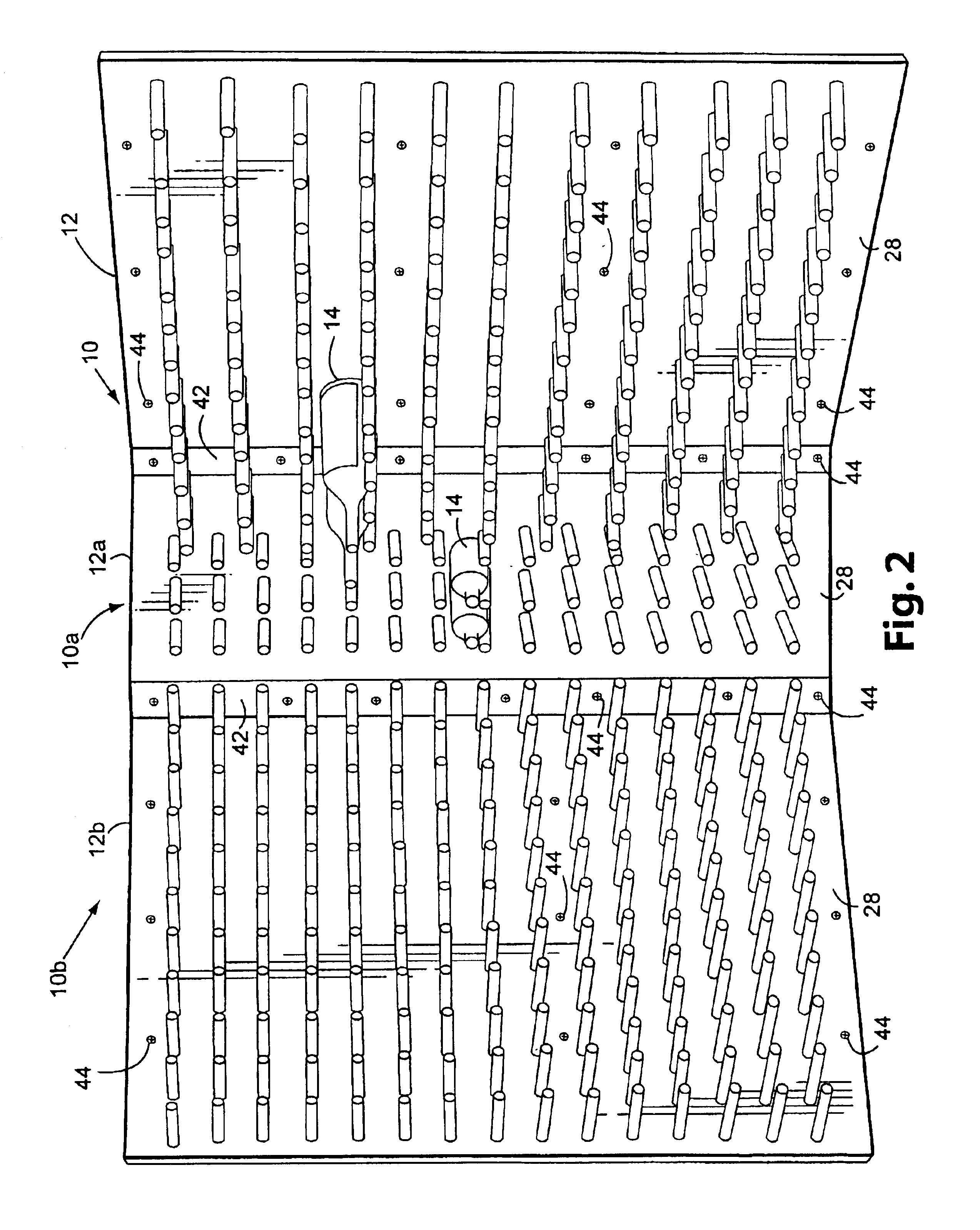
To produce a wall mount wine rack 10 shown in FIGS. 1 and 2, e.g. at an offsite fabrication machine shop, using a computer software driven "Trumfp 360" laser torch cutting machine, programmed to cut 3 / 8 inch diameter holes and positioned over a 4 ft..times.8 ft. rectangular machine finish (No. 4 "satin") 11 gauge (1 / 8 inch) standard stainless steel wall steel sheet which is to be fabricated into a vertical side wall support member 12 of a wine rack 10 adapted for storing 750 ml wine bottles 14 thereon, with the steel sheet positioned flat over a water-filled quenching reservoir, cut as wine bottle support rod mounting holes 16 in wine rack 10, ca. 3 / 8 inch holes 16 in the steel sheet (which will permit the threaded shank 18 of a 3 / 8-24 inch.times.1 / 2 inch SAENF stainless steel machine bolt 20 to be inserted and slip fitted therein) at 3.42 inch intervals in rows 3.419 inches apart, beginning 3.463 inches vertically and 3.490 inches horizontally from the corner thereof corresponding ...

example 2

To produce a wall mounted wine rack 10 otherwise corresponding to the wall mounted racks 10 of Example 1 but adapted for mounting 375 ml wine bottles thereon, follow the same procedure except cut the mounting holes 16 in the 4 foot.times.8 foot steel sheets at 2.823 inch intervals in rows 3 inches apart, beginning at 1.412 inches vertically and 2.850 inches horizontally from the upper right hand corner thereof. Adjust the margins for the installation holes cut in the custom cut corner steel sheet used to form corner support member 12a so that they are similarly positioned symmetrically therein.

Optionally, instead laser cut the support rod mounting holes 16 in one or more of the steel sheets used to produce side wall support members 12 and / or the custom cut steel sheet used to produce the corner support member 12a in the manner described in Example 1 only in a partial area of one or more of the support members and cut the rest of the mounting holes at the intervals and at a distance ...

example 3

To produce a wall mounted wine rack 10 otherwise corresponding to the wall mounted racks of Example 1, adapted for mounting 1.5 liter wine bottles thereon, fabricate the internally threaded cavities 32 in 9 inch lengths of stainless steel mounting rods and cut the support rod mounting holes 16 in the steel sheet used to produce the side wall support members 12 at 4.364 inch intervals in rows 4.546 inches apart, beginning at 2.182 inches vertically and 3.480 inches horizontally from the upper right hand corner thereof. Adjust the margins for the holes in the custom cut corner steel sheet 42 so that the holes are symmetrically positioned therein.

In the manner described in Example 2, create the support rod mounting holes 16 in one or more of the steel sheet used to produce the side wall support members 12 in the manner described in Example 1 only in a partial area of the support member and create them at the intervals and at a distance between the rows as described in this example in t...


PUM


Abstract

Disclosed is a wine rack, large versions of which are adapted to be installed against a wall of a room or as a free standing wall separated from the walls of a room, which is a monolithic flat rigid sheet to which has uniformly mounted in rows through holes therein a like number of wine bottle support rods which project perpendicularly and parallel to each other from one or both faces of the sheet so that two wine bottles of varying sidewall diameter can be stored on three of the rods without their side-walls touching and whose essential elements can be fabricated offsite by forming uniform rows of holes in a monolithic sheet of stainless steel; fitting in the holes machine bolts whose threaded shank ends project beyond a face of the steel sheet; bonding the heads of the bolts to the opposite face of the steel sheet so that their threaded ends project axially perpendicularly, rigidly and parallel to each other; and forming a female threaded cavity in one end of a plurality of wine bottle support rods. The thus-fabricated structural parts of the wine rack are then transported to the installation site, where the rods are coupled to the projecting ends of the bolts. A plurality of the thus-fabricated wine rack are mounted side-by-side vertically on a wall of a room at the installation site or one of them can be installed as free standing version which is stabilizing from bending or swaying at its base. A free standing version with wine bottle support rods projecting from both faces thereof can similarly be produced using short lengths of threaded steel rods which, when inserted in the holes in the steel sheet, its ends project a short distance beyond each face of the steel sheet so that the internally female threaded ends wine bottle support rods can be mounted on both ends thereof.

Description

This invention relates to a novel wine rack, to installations comprising it, to a kit containing the elements thereof adapted for onsite assembly thereof and to a method for the fabrication of its essential elements offsite and the onsite assembly thereof.A wine cabinet which employs a plurality of rods mounted thereon perpendicularly at one end thereof and parallel to each other in a plurality of rows on a face of a vertical flat support member, at intervals such that x+1 adjacent rods in the same row will support x number of wine bottles, is known in the prior art. See U.S. Pat. No. 6,361,129. A wine rack in which the body of the wine bottles is supported by a pair of support pegs and the neck thereof is positioned in a hole in an upright panel is disclosed in U.S. Pat. No. 4,382,065. A wine rack which is large enough to cover most or all of the surface of a wall of a room and adapted to be mounted vertically on or against the wall, which consists essentially of a rigid flat suppo...

Claims


Application Information

Patent Timeline
Patent Type & Authority Patents(United States)
IPC IPC(8): A47B73/00
CPCA47B73/00
Inventor WOODS, DANIEL
Owner WOODS DANIEL
Why Eureka
Try Eureka