Variable slit width device for spectroscope

a spectroscope and variable slit technology, applied in the field of variable slit width devices, can solve the problems of not being used, however, and not being practical

Inactive Publication Date: 2004-07-20
YOKOGAWA ELECTRIC CORP
View PDF1 Cites 7 Cited by
  • Summary
  • Abstract
  • Description
  • Claims
  • Application Information

AI Technical Summary

Problems solved by technology

However, there was a problem in the variable slit width device for a spectroscope shown in FIG. 4 that it has not been used in a narrow space such as an optical path returning part such as a 2 path, 4 path, 8 path monochromator serving as an optical unit of the dispersible monochromator spectrum analyzer.
That is, even if the slits 2 are positioned in a narrow space such as an optical path returning part such as a 2 path, 4 path, 8 path monochromator, the entire variable slit width device for a spectroscope including the housing part 8 has to be carried in such a narrow space, which is however not practical.
Further, there is another problem that the slit defining members 2 do not uniformly operate right and left, a width dimension and the central position in the width direction do not become in theoretical values owing to a manufacturing error of the right and left screws of the closing screw 64, thereby causing error.

Method used


Image

  • Variable slit width device for spectroscope
  • Variable slit width device for spectroscope
  • Variable slit width device for spectroscope

Examples


Embodiment Construction

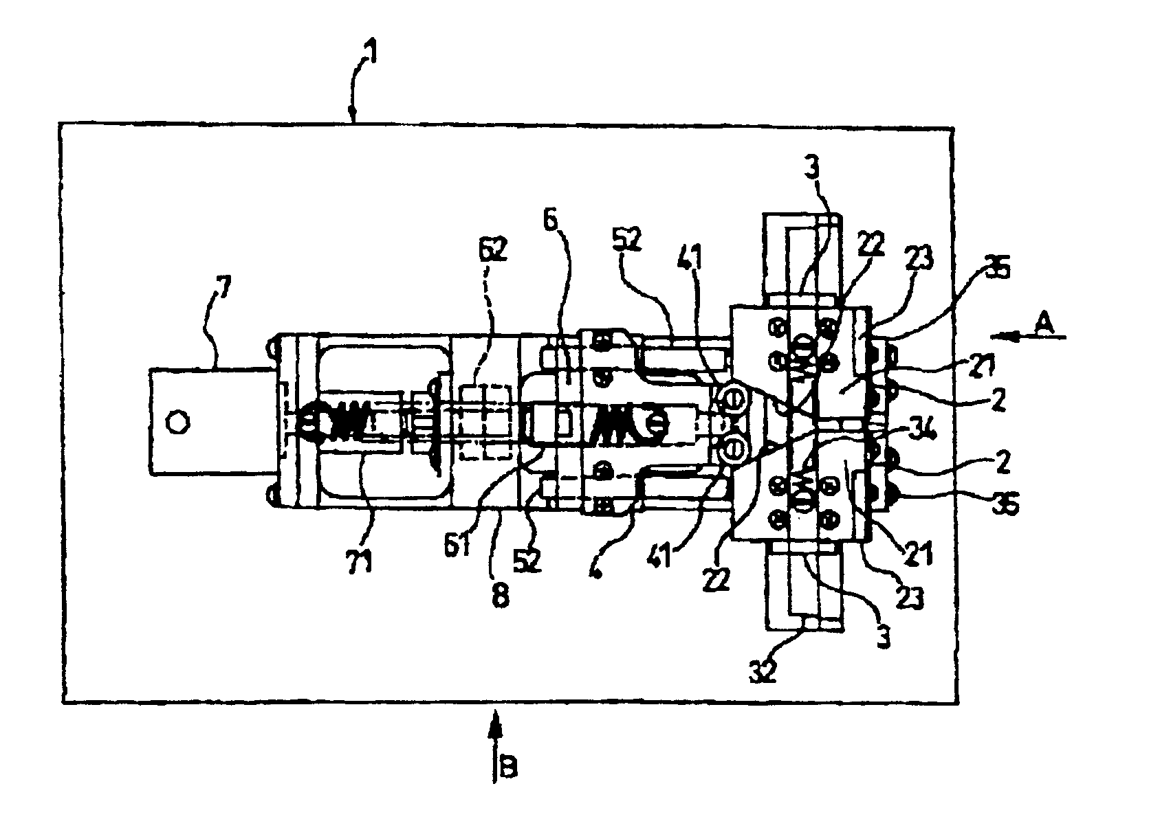
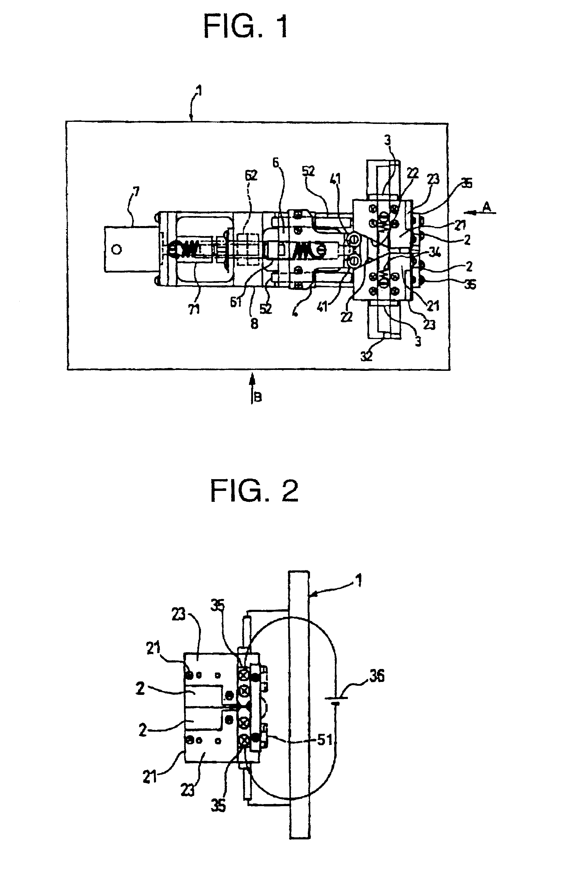
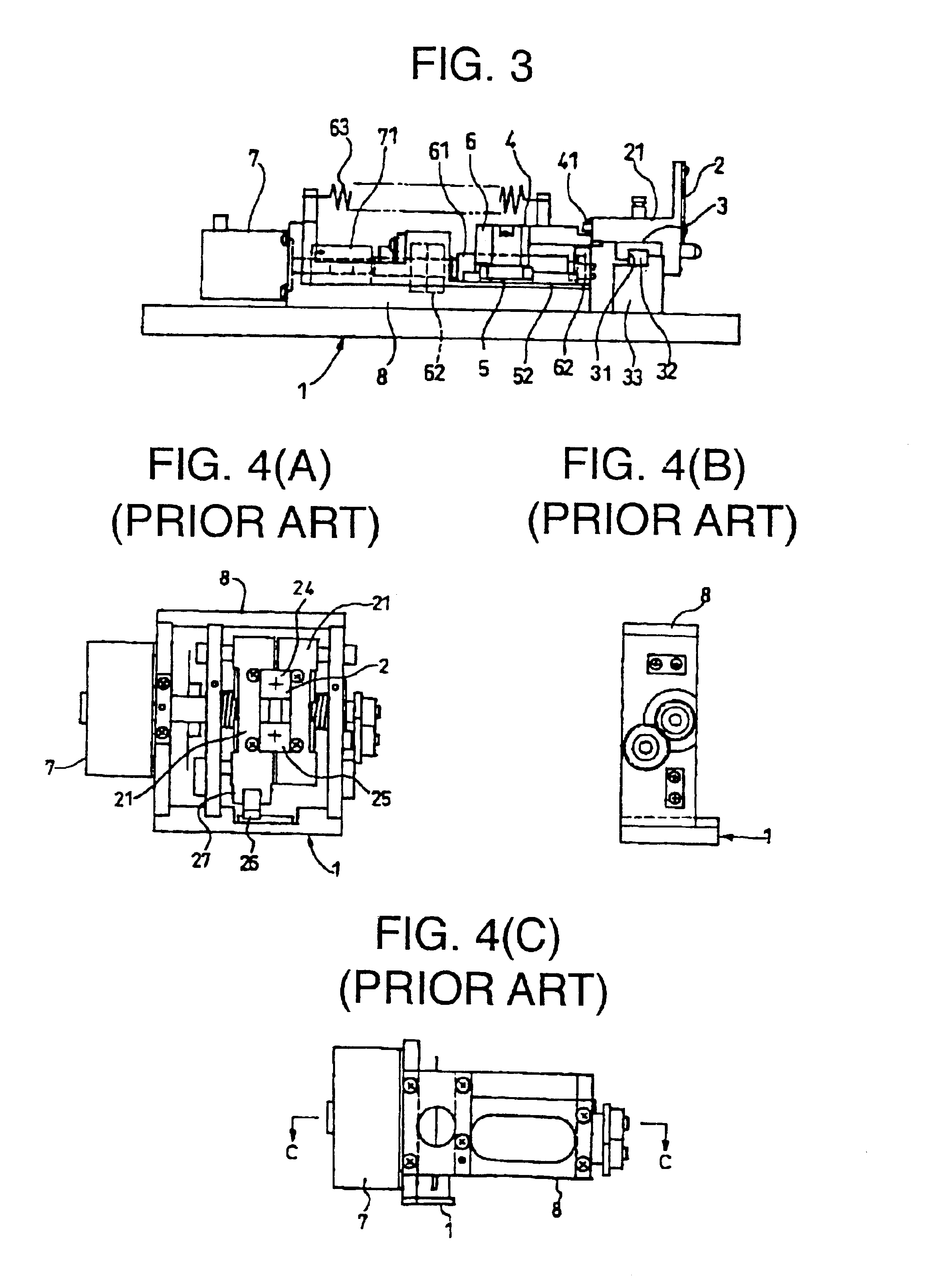
A variable slit width device for a spectroscope of the invention is now described with reference to the attached drawings. FIG. 1 is a view showing a variable slit width device for a spectroscope according to the invention, FIG. 2 is a view as viewed from the arrow A in FIG. 1 and FIG. 3 is a view as viewed from the arrow B in FIG. 1.

As shown in FIG. 1, the variable slit width device for a spectroscope has a fixed part 1. The fixed part 1 is fixed to a dispersible monochromator spectrum analyzer and other optical units requiring a slit part and a driving part for controlling and driving the slit defining members of the slit part so as to open or close the slit part, as described below.

The slit part is described next. Slit defining members 2 are disposed on the side surfaces of a pair of slit holders 21 so as to protrude relative to the slit part and slit driving part by slit pressers 23, as also shown in FIG. 2. A pair of electrodes 35 are attached to the side surfaces of the pair o...


PUM


Abstract

A variable slit width device for a spectroscope which can be used in a narrow space, be widely variable, and be set in slit width with high accuracy. The variable slit width device includes a pair of freely rotatable rotary parts for pressing inclined guide parts of a pair of slit holders, pressing parts for supporting the pair of rotary parts, and linear guides having guide parts formed at the lower surfaces thereof and extending horizontally in a direction crossing with guide rails at right angles. The pressing parts are fixed to the linear guides, the guide rails are fitted to the guide parts of the linear guides, feed nuts are fixed to the pressing parts, feed screws are engaged with the feed nuts. Bearings are provided for rotatably supporting the feed screws, preload springs for preloading the feed nuts and the feed screws, a slit driving part for rotatably driving the feed screws, and a housing part for fixing thereto the guide rails, the bearings and the motor.

Description

1. Field of the InventionThe invention relates to a variable slit width device to be applied to a spectroscope, particularly to an optical spectrum analyzer.2. Related ArtA conventional variable slit width device for a spectroscope is now described with reference to FIGS. 4(A), 4(B), 4(C), and FIG. 5. In FIGS. 4(A), 4(B), and 4(C), depicted by 1 is a fixed part of the variable slit width device for a spectroscope. The fixed part 1 is fixed to such as an dispersible monochromator optical spectrum analyzer and other optical devices. A housing part 8 is fixed to the fixed part 1. The housing part 8 houses therein a slit part and a driving part for driving slits so as to open or close the slit part.The slit part is now described. In FIGS. 4(A), 4(B), 4(C), depicted by 2 are slit defining members, which are parallel with two opposite surfaces of the housing part 8, and disposed in parallel with each other in a horizontal direction. Depicted by 24 is a blade face 24 of the slit defining m...

Claims


Application Information

Patent Timeline
Patent Type & Authority Patents(United States)
IPC IPC(8): G01J3/00G01J3/04
CPCG01J3/04
Inventor ISHIKAWA, EIJIANDO, HIROSHI
Owner YOKOGAWA ELECTRIC CORP
Why Eureka
Try Eureka