Hydrodynamic bearings having strain sensors

a technology of strain sensor and bearing, which is applied in the direction of force measurement by measuring optical property variation, simultaneous indication of multiple variables, and apparatus for force/torque/work measurement, etc. it can solve the problems of bearing bearing bearing bearing dynamic load, bearing wear, and bearing bearing bearing bearing bearing bearing bearing bearing bearing bearing bearing bearing bearing bearing bearing bearing bearing bearing bearing bearing bearing bearing bearing bearing bearing bearing bearing bearing bearing bearing bearing bearing bearing bearing bearing bearing bearing bearing bearing bearing bearing bearing bearing bearing bearing bearing bearing bearing bearing bearing bearing bearing

Inactive Publication Date: 2004-07-27
BEARINGS PLUS INC A TEXAS
View PDF21 Cites 43 Cited by
  • Summary
  • Abstract
  • Description
  • Claims
  • Application Information

AI Technical Summary

Problems solved by technology

Regardless of the design of the hydrodynamic bearing, as the shaft rotates imbalance and eccentricity can cause the shaft to exert a dynamic load on the bearing, particularly on the bearing pads.
This can lead to fretting wear on the pad support surfaces and fatigue of the babbit metal of the bearing, and eventually lead to bearing destruction which, in turn, can cause catastrophic failure.
Prior art attempts to measure the loads on hydrodynamic bearings during use have not been successful due to various factors.
In particular, failures have resulted from the environmental conditions under which the bearings operate (namely high temperatures, high pressures and moisture), and from the design of the measuring devices themselves which, when installed, affected bearing performance.
In use, the mounting of the Halloran device can, itself, adversely affect bearing performance.
In addition, the piezo-electric load cell is vulnerable to failure in high temperature environments.
Thus, dynamic load sensors (an example of which is the Halloran device) are not currently utilized in the industry.
Bearings can also become subject to instability which manifests itself as oil whirl or oil whip.
Left uncorrected, this phenomenon is catastrophic and can destroy the bearings, seals, and the rotor very quickly.
Oil whip is a dangerous condition where rotor damping is unable to limit the rotor's motion so that displacement amplitudes continue to grow until halted by contact with stationary parts, such as internal seals.
This condition leads to high friction levels which will overheat the babbit metal and leads to rapid destruction of the bearing, rotor journal, and the machine seals.
Although these probes have been useful, they suffer from significant drawbacks.
Such probes are costly to install in machines and may not be able to be installed in all machines.
In addition, they are subject to run out problems because the effectiveness of the probes (which are electromagnetic) relies on the continuity of the surface of the shaft.
Even small imperfections in the surface of the shaft can lead to false read outs, especially at high speeds.
Also, the proximity probes are often permanently damaged by their operating environment (high temperatures, forces, etc.) and are costly to replace.
These sensors can also be unreliable due to their operating environment, and further lack the sensitivity to detect damaging levels of vibration at speeds above 40,000 to 50,000 rpm.
The disadvantages with such probes increases when trying to use the probes with small rotors, such as those found in turbo chargers and micro turbines, where it becomes increasingly difficult to accurately measure displacement with the probes.
Such probes also do not measure the dynamic loads which can cause bearings to wear, as discussed above.

Method used


Image

  • Hydrodynamic bearings having strain sensors
  • Hydrodynamic bearings having strain sensors
  • Hydrodynamic bearings having strain sensors

Examples


working example

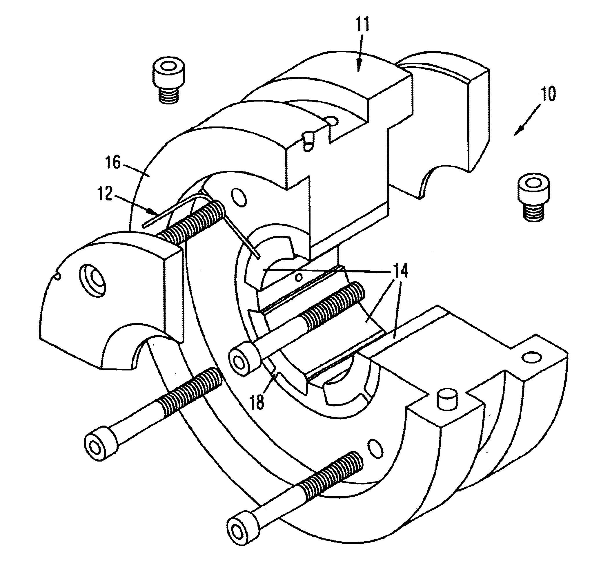
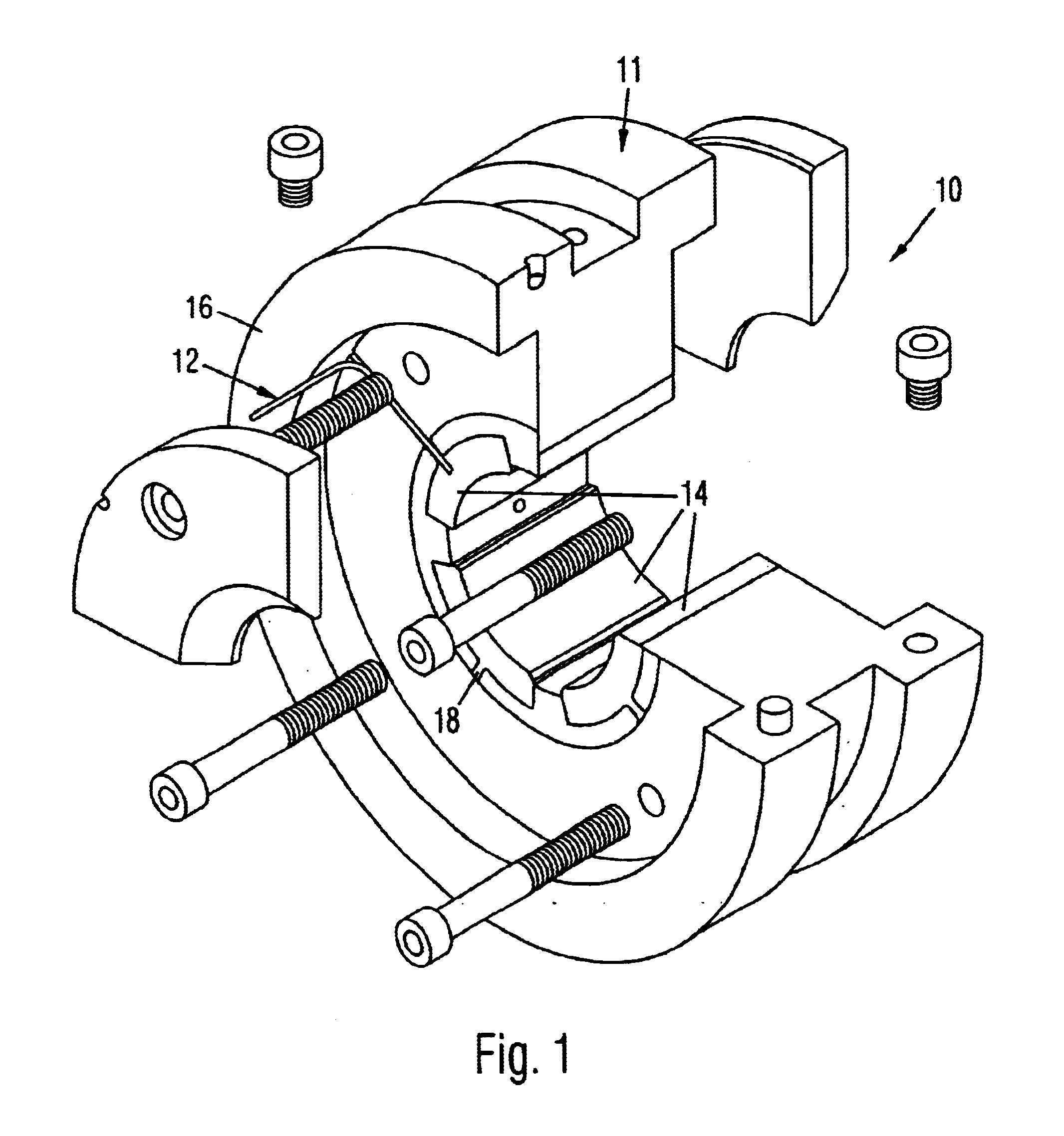
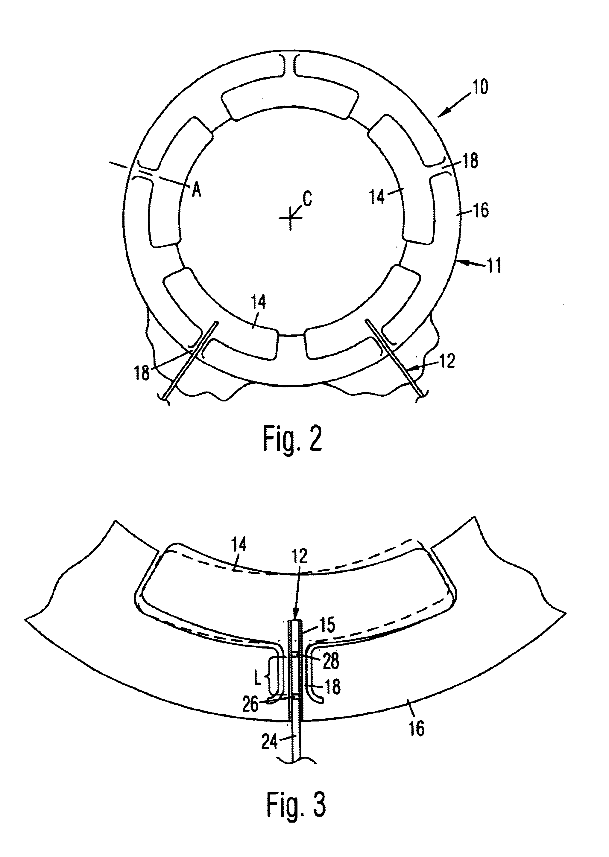
The following example was performed by utilizing an FFPI sensor fitted into a 2.5 inch, four (4) pad, ball-in-socket bearing of the type illustrated in FIGS. 4-6 and described herein. Specifically, the FFPI sensor was inserted into the bolt securing the ball to the housing, thus ensuring that the load was transmitted from the pivot to the bolt and sensor. A test rig (not shown) having a three-disk rotor characteristic of many industrial machines capable of running up to 10,000 rpm was utilized with the bearing assembly. Two forward critical speeds existed for the rotor-bearing test system. Charts showing the load vs. voltage calibration curve, measured dynamic load and computed dynamic load for this example are shown in FIGS. 10-12. FIGS. 13 and 14 illustrate the measured displacement and calculated displacement for the same 2.5 inch, four (4) pad, ball-in-socket bearing utilizing standard 200 mV / mil proximity probes utilized throughout the industry and available from suppliers such...


PUM

PropertyMeasurementUnit
output voltageaaaaaaaaaa
electrical voltageaaaaaaaaaa
tensionaaaaaaaaaa

Abstract

A hydrodynamic bearing includes a fiber optic sensor for measuring static and dynamic bearing forces or loads during operation. The fiber optic sensor is positioned within the bearing through the most direct load path, which is through the pad support for a tilting pad style bearing. In additional to being positioned in the pad support of a tilting pad bearing, the sensor is also placed 1) inside the pad support or on the pad support structure, and 2) oriented perpendicularly with the shaft centerlines. After the sensor location is chosen and the sensor is properly positioned, a calibration procedure is utilized to determine the relationship between the radial load and measured strain for the specific bearing. Once the calibration factor has been determined, the sensor may be utilized in the bearing to measure load during operation.

Description

The invention relates generally to hydrodynamic bearings including strain sensors and, more particularly, to hydrodynamic bearings containing fiber optic sensors for measuring static and dynamic bearing loads on the bearings during operation.BACKGROUND OF RELATED ARTHydrodynamic or fluid film bearings are widely employed as rotor supports in industrial machinery having high horsepower and high loads. A basic purpose of such bearings is to provide a relatively frictionless environment to support and guide a rotating shaft. Various designs for hydrodynamic bearings have evolved over time. Some bearings such as the lemon bore and pressure dam designs have a fixed geometry, without moving parts. In contrast, other bearings have a variable geometry, with the bearing pads flexing, pivoting or otherwise moving in response to changing load conditions in order to stabilize the bearings during use. Examples of variable geometry bearings include the ball-in-socket design, the rocker design, an...

Claims


Application Information

Patent Timeline
Patent Type & Authority Patents(United States)
IPC IPC(8): G01L1/24F16C17/03F16C17/24G01L5/00
CPCF16C17/03F16C17/24G01L5/0009F16C2360/24F16C2233/00
Inventor PEREZ, ROBERT X.IBANEZ, NATIVIDAD S.
Owner BEARINGS PLUS INC A TEXAS
Why Eureka
Try Eureka