
Method for detecting and correcting sensor failure in oil and gas production system

a technology of oil and gas production system and sensor failure, applied in the field of production system, can solve problems such as sensor failure, and achieve the effect of detecting and correcting sensor failur

Inactive Publication Date: 2004-08-03
ABB AS
View PDF12 Cites 35 Cited by
  • Summary
  • Abstract
  • Description
  • Claims
  • Application Information

AI Technical Summary

Benefits of technology

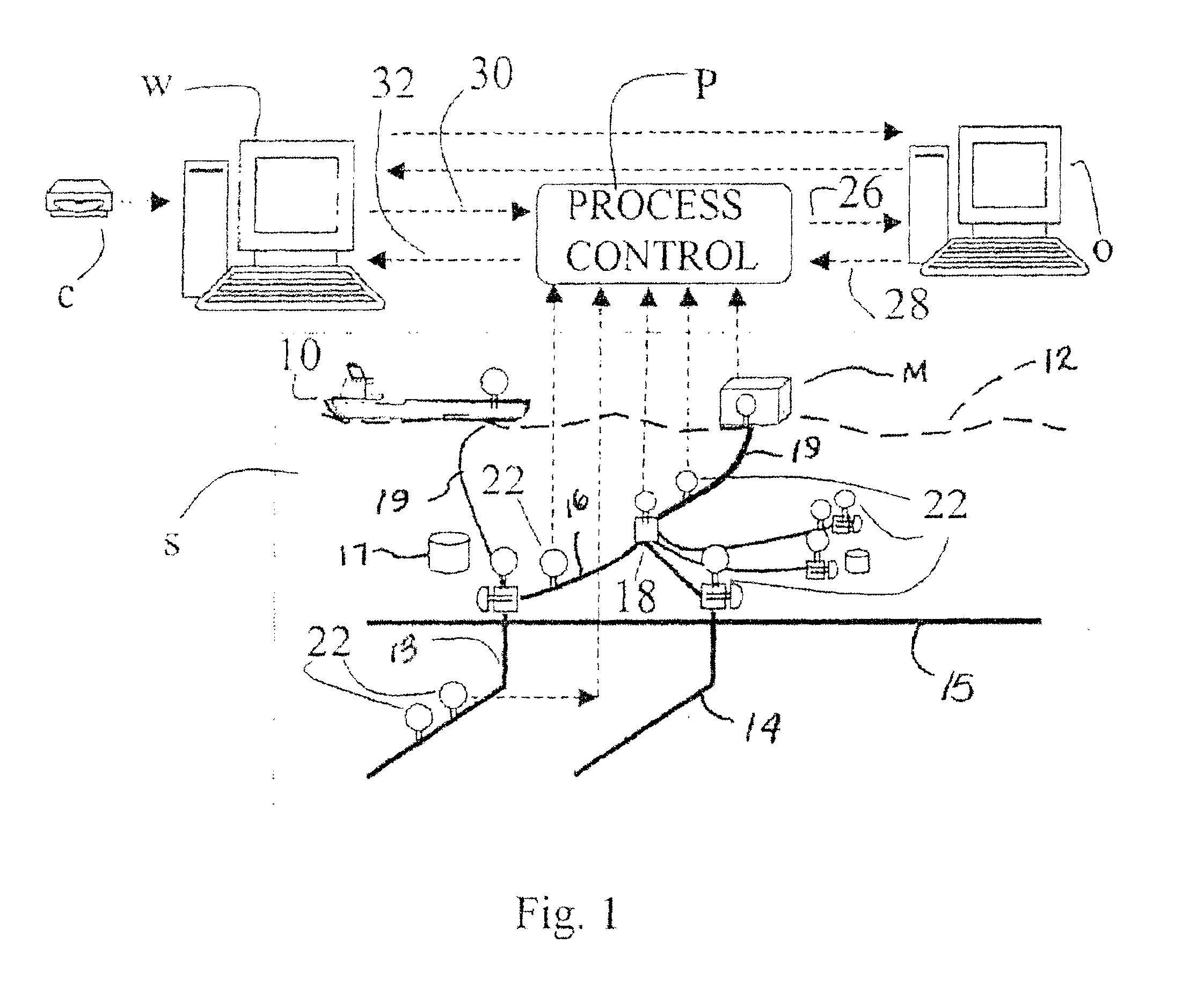
A preferred embodiment of the invention is embedded in an oil and gas production administrative system W, such as shown according to FIG. 1, which allows for the specification of a comprehensive production system from which connected subsystems may be selected for processing by the invention. The surrounding administrative system W also allows for repeated and parallel execution of multiple versions of the present invention.

Problems solved by technology

If such is not the case, a failure of the sensor is indicated.

Method used


Image

  • Method for detecting and correcting sensor failure in oil and gas production system
  • Method for detecting and correcting sensor failure in oil and gas production system
  • Method for detecting and correcting sensor failure in oil and gas production system

Examples


Embodiment Construction

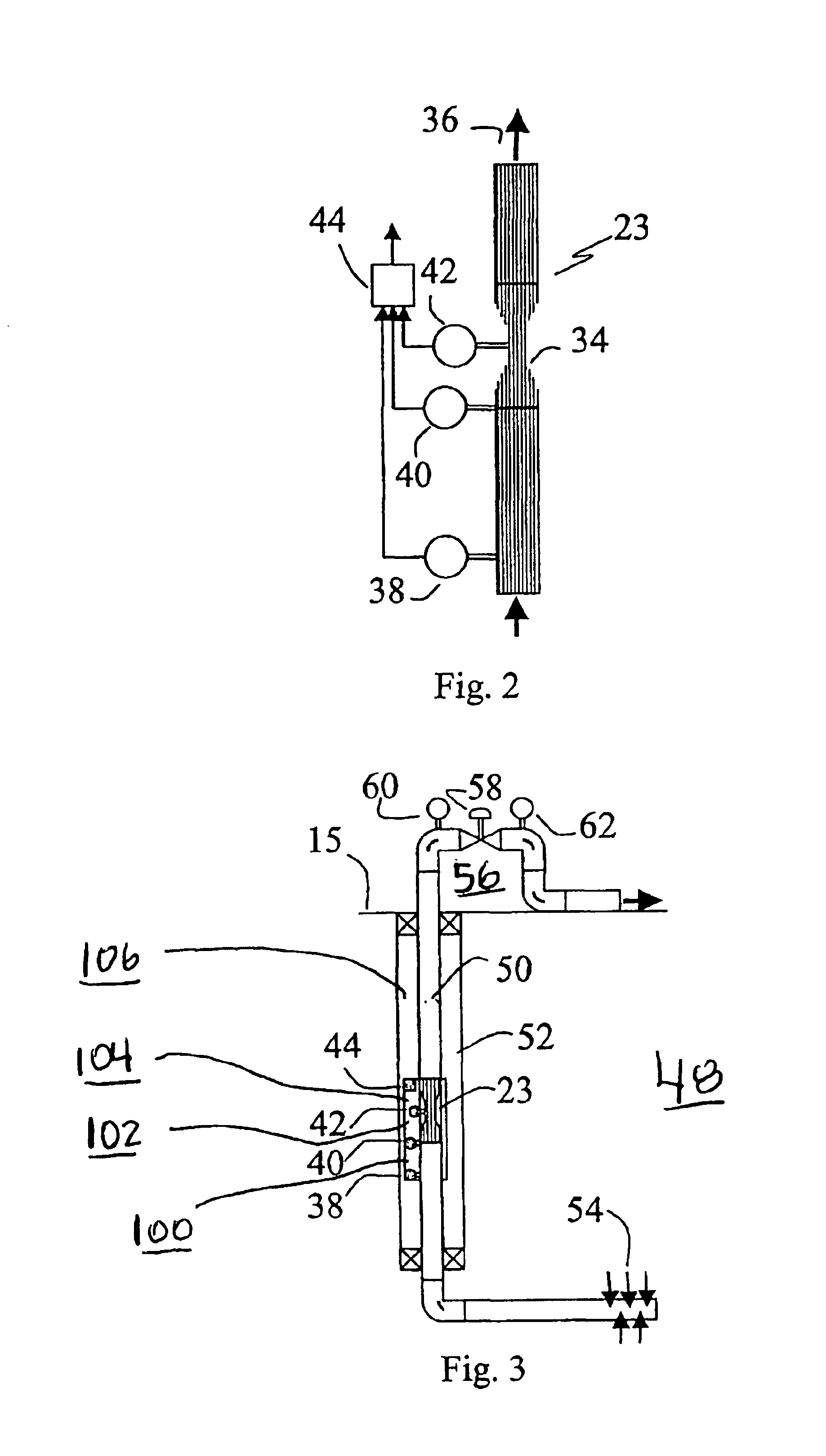
As an example result, the foregoing analysis was performed on a sensor layout of the type shown in FIG. 3. The relevant part of the production system S in this example runs from the pressure and temperature gauge 38 down-hole in FIG. 3 to the well head pressure and temperature gauge 60 in FIG. 3.

In this example there is only one relevant fluid flowing through the well, an oil with an unknown flow rate and a known composition.

The relevant part of the production system S is subdivided into the following subsystems;

a lower tubing 100 from the down-hole sensor 38 to the inlet of the venturi 40 in FIG. 3;

a venturi inlet tube 102 from the gauge 40 to the gauge 42 in FIG. 3;

a venturi outlet tube 104 from the gauge 42 to the top of the venturi downhole flow meter 23 in FIG. 3; and

an upper tubing 106 from the top of the venturi downhole flow meter 23 to the gauge 60 in FIG. 3 in the well consisting of a number of pipe segments with different properties.

The measured flow properties in the rel...


PUM


Abstract

Sensor failure in an oil and gas production system is monitored and detected by checking the consistency of the measurements of the sensor in question using a computer-based process model with the measurements of the other sensors in the system. The present invention also generates a back-up value for a failing sensor with the process model by identifying the value that is most consistent with the measurements of the other sensors in the system.

Description

BACKGROUND OF INVENTION1. Field of InventionThe present invention relates to production systems for the production of oil and gas, and in particular to the validation of sensors installed in such systems for measuring physical properties of the flow through the production system.2. Description of the Prior ArtOil and gas production systems typically contain sensors for measuring physical properties of the flow. Sensor measurements in the production system are for instance used as input (initial values) for simulations of the reservoir.A well-known problem in the oil industry is that sensors in the production system become inaccurate, or even fail completely, after some time in operation. The problems are mainly due to the harsh conditions under which such equipment is operated, such as the high pressure, the high temperature, or the corrosive environment present in the production system.New oil wells are being equipped with sensors increasingly often. An example of a sensor that is ...

Claims


Application Information

Patent Timeline
IPC IPC(8): G01D3/08G01N33/00G05B9/02G01D1/18G01N33/26G05B
CPCG01D3/08G01N33/007G05B9/02G01F1/74
Inventor VAN DER GEEST, ROBERT ANTON BERNARDALLEN, JOHNMORUD, SVEIN ARNEBRINGEDAL, BJORN OYVIND
Owner ABB AS
Learn More