Portable telephone

a portable telephone and telephone body technology, applied in the field of portable telephones, can solve the problem of too small housing siz

Inactive Publication Date: 2004-08-31
SONY CORP
View PDF16 Cites 37 Cited by
  • Summary
  • Abstract
  • Description
  • Claims
  • Application Information

AI Technical Summary

Problems solved by technology

This is caused partly due to that a size of the housing is too small compared to the electromagnetic wavelength used in the radio communications, i.e., less than one wavelength thereof.

Method used


Image

  • Portable telephone
  • Portable telephone
  • Portable telephone

Examples


embodiment 1

Preferred Embodiment 1

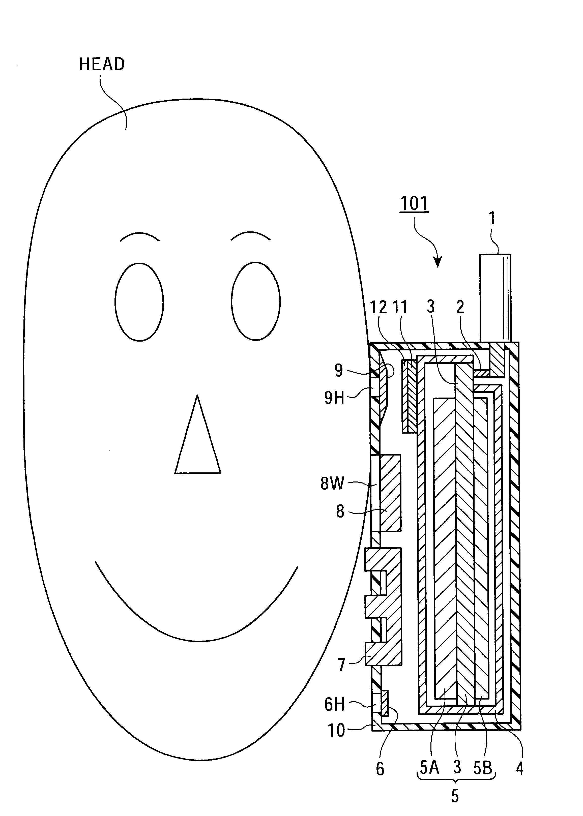
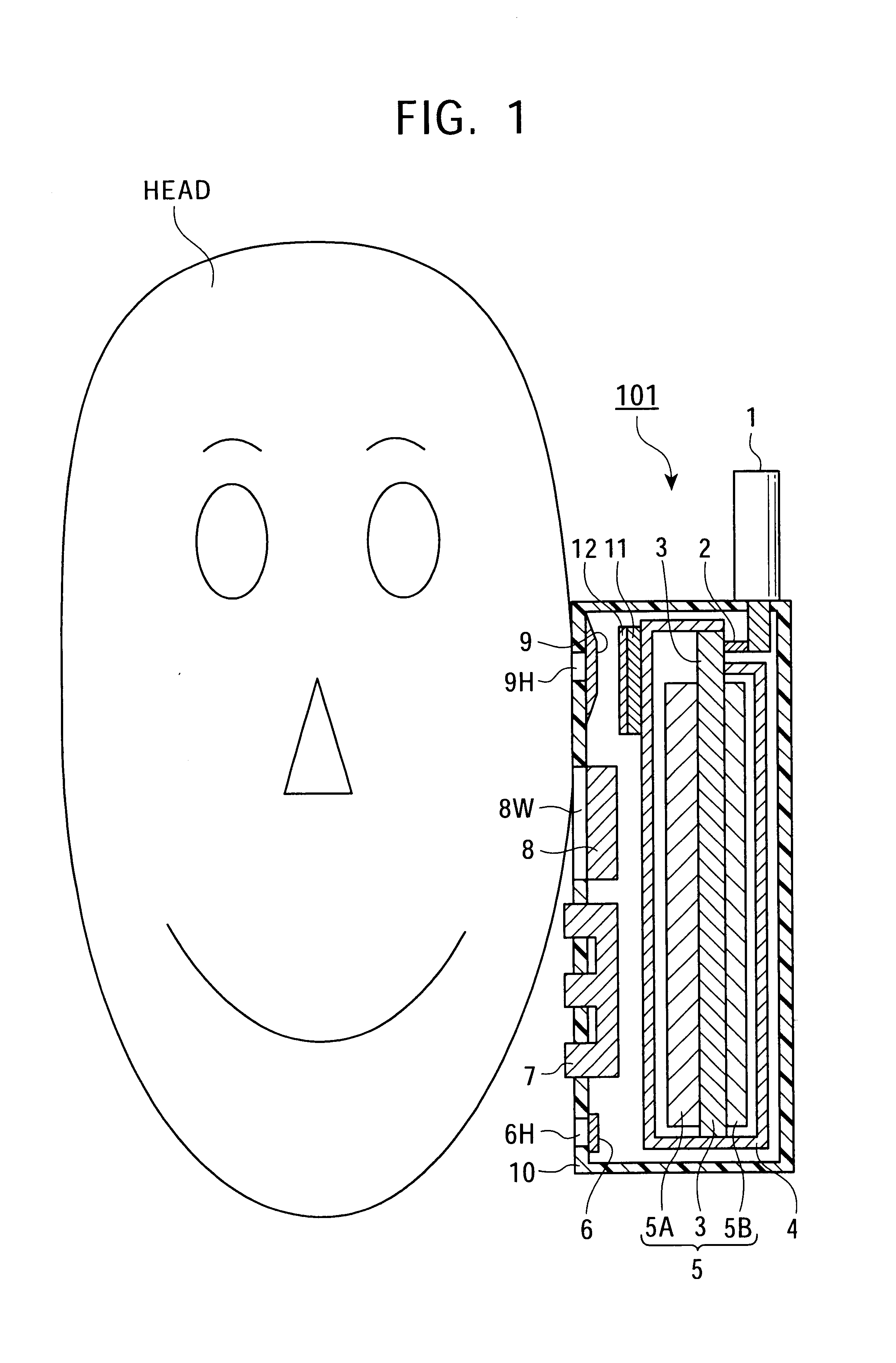
With reference to FIG. 1, a schematic diagram of a portable telephone according to one embodiment of the present invention is shown. As shown in this drawing, a portable telephone 101 is used in close proximity to a head (HEAD) of the user.

The portable telephone 101 of the invention has an antenna 1, a feeder section 2, a printed board 3, a shield case 4, semiconductor integrated circuits 5A, 5B, a microphone 6, a keypad 7, a liquid crystal display (LCD) 8, a speaker 9 and an insulated housing 10. Further, in a space between the shield case 4 and the housing 10, an electromagnetic wave absorption layer 11 which contains a magnetic loss material is formed in close proximity to the speaker 9. Still further, an electromagnetic wave reflection layer 12 which contains a magnetic reflection material is formed on the electromagnetic wave absorption layer 11. A size of the housing 10 in its longitudinal directions is, for example, 120 mm.

The antenna 1 for signal transm...

embodiment 2

Preferred Embodiment 2

With reference to FIG. 4, a schematic diagram of a portable telephone according to a second embodiment of the invention is shown. As shown in FIG. 4, in this portable telephone 102 according to the second embodiment of the invention, its electromagnetic wave absorption layer 11 and its electromagnetic wave reflection layer 12 are provided, not on the surface of the shield case 4 as practiced in the portable telephone 101 of the first embodiment of the invention indicated in FIG. 1, but on a side of its housing 10.

The electromagnetic wave reflection layer 12 thereof is formed firmly in contact with the housing 10 thereof. The electromagnetic wave absorption layer 11 thereof is formed in contact with the electromagnetic wave reflection layer 12 thereon, and closer to its shield case 4 than the electromagnetic wave reflection layer 12 is. A thickness of the electromagnetic wave absorption layer 11 is set, for example, at 2 to 3 mm, and a thickness of the electroma...


PUM


Abstract

The portable telephone capable of more effectively reducing the electromagnetic energy to be radiated therefrom and absorbed by the human body during its use is provided. The portable telephone is comprised of: an antenna; a microphone; a transmitting circuit for modulating a first audio signal to produce a first radio signal, and transmitting the same; a receiving circuit for demodulating a second radio signal received via the antenna, and reproducing a second audio signal; a receiver for outputting an audio sound corresponding to the second audio signal; a printed circuit board on which the receiving and the transmitting circuits are mounted; a shield case surrounding the printed circuit board so as to suppress the electromagnetic interference between the printed circuit board and the antenna; the housing for accommodating the shield case and so on; the electromagnetic wave absorption layer including a magnetic loss material, formed at least in a part between the shield case and the housing; and the electromagnetic wave reflection layer including a magnetic reflection material, formed between the housing and the electromagnetic wave absorption layer.

Description

1. Field of the InventionThe present invention relates to a portable telephone and, in particular, it relates to a portable telephone capable of minimizing absorption of an electromagnetic energy radiated therefrom by a human body when in use thereof.2. Description of the Related ArtFIG. 6 is a schematic diagram showing a conventional portable telephone. As shown in FIG. 6, a portable telephone 201 is used being held in a close proximity to a head (HEAD) of a user. The portable telephone 201 is comprised of an antenna 31, a feeder 32, a printed board 33, a shield case 34, semiconductor integrated circuits 35A and 35B, a microphone 36, a keypad 37, a liquid crystal display 38, a speaker 39 and an insulated housing 40.The antenna 31 for use of signal transmission and reception is allowed to project upward from an upper edge of the housing 40 for transmitting electromagnetic waves to a base station in a transmission mode and receiving electromagnetic waves from the base station in a re...

Claims


Application Information

Patent Timeline
Patent Type & Authority Patents(United States)
IPC IPC(8): H01Q1/24H01Q17/00H04B1/38H04B1/3822H04M1/02
CPCH01Q1/245H01Q17/001H04B1/3838
Inventor TOYODA, JUNICHIOKAYAMA, KATSUMI
Owner SONY CORP
Why Eureka
Try Eureka