
Transmission light-scattering layer sheet and liquid crystal display

a technology of liquid crystal display and light-scattering layer, which is applied in the direction of optics, instruments, static indicating devices, etc., can solve the problems of increasing the proportion of loss of reflected light, increasing production costs, and high cost, and achieves bright display, high directionality, and high illumination

Inactive Publication Date: 2004-09-07
DAICEL CHEM IND LTD
View PDF24 Cites 7 Cited by
  • Summary
  • Abstract
  • Description
  • Claims
  • Application Information

AI Technical Summary

Benefits of technology

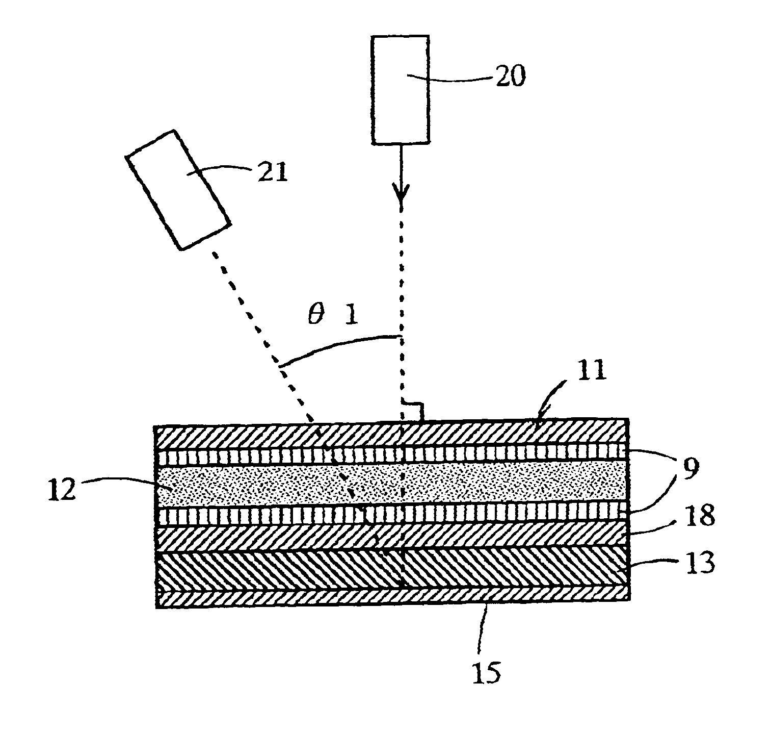
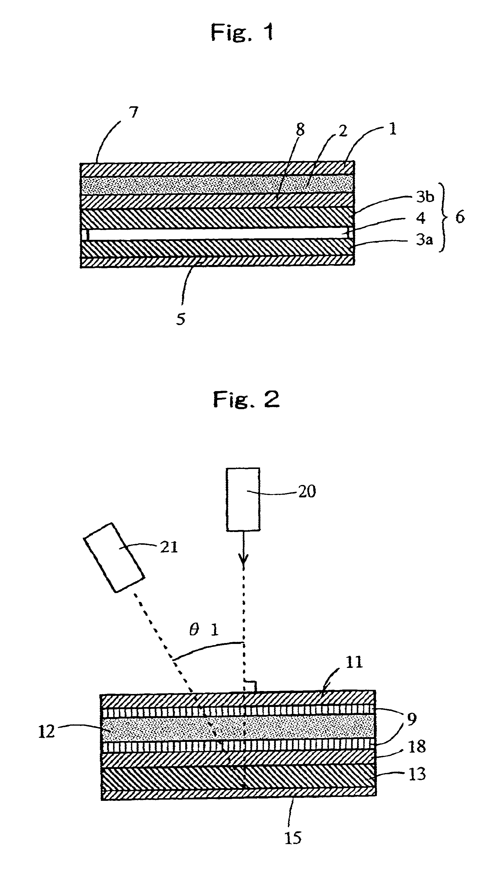
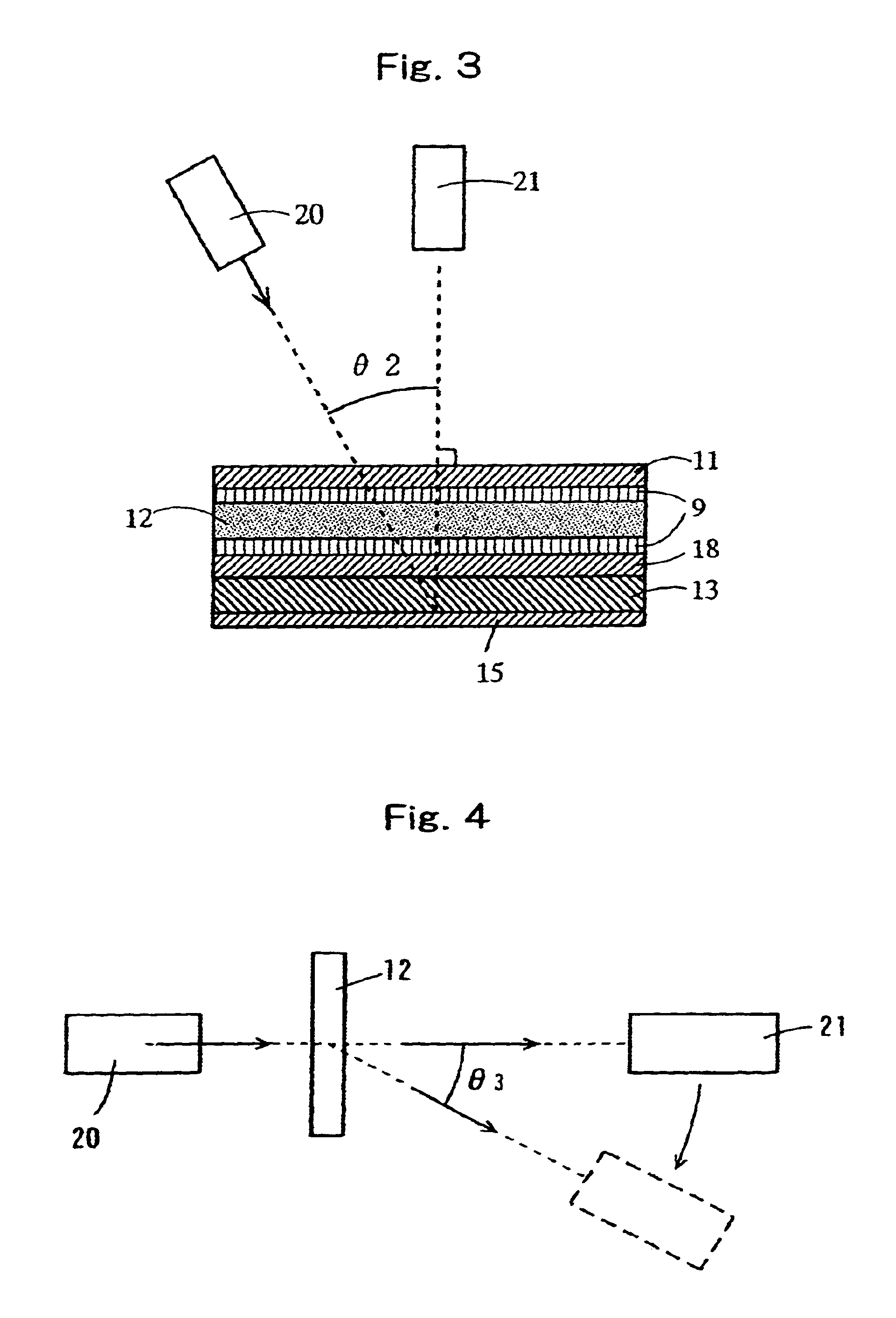
The droplet phase structure of the light-scattering layer has a regularity of average distance between droplet centers (average interphase distance). That is why, the light incident on the sheet is directed toward the specific direction by Bragg reflection. Therefore, even though the sheet is provided with a reflective liquid crystal display device, the scattered light can be directed in a given direction (directed-type diffusion) and the display screen can be highly brightened. As a result, the problem unable to be solved by a conventional particle-dispersion type transmittable light-scattering sheet, that is, reflecting a light source configuration (or image) on the panel can be avoided.
According to the present invention, since the light-scattering layer has the specific phase separation structure, not only the high directionality but also the light-scattering property can be imparted to a transmitted and scattered light, the whole screen can be brightly displayed. That is why, even in a color display unit having large display surface area, the display screen can be illuminated highly. Therefore, the transmitted light-scattering sheet of the present invention is preferably applied to a reflective liquid crystal display device, in particular, a colored liquid crystal display device for portable information terminals. Further, even in a colored reflective liquid crystal display device, the display screen can be displayed with high image-quality, vividness and brightness, and a display of a high definition and high luminance can be realized. Furthermore, according to the method of the present invention, the transmittable light-scattering sheet having the substantially isotropic phase separation structure can be produced with the use of spinodal decomposition of the liquid phase at low cost.

Problems solved by technology

In case where a color filter is used, the proportion of loss of reflected light is increased and the above diffusion reflecting plate (scattering plate) system cannot impart enough brightness to the display screen.
However, in order to enhance the directionality by scattering and reflecting plate system, it is necessary that configuration and distribution of uneven part of the reflecting plate is accurately controlled, and it requires a high cost.
However, in order to impart directionality to a transmitting type light-scattering sheet by polymerization with utilizing the above holography, complicated method of producing, and as a result, raises the production cost is required.
Thus, the directionality can not be imparted to the scattered light, and it is difficult that brightness of the display surface is advanced.
Particularly, in respect to the particle dispersed sheet, the brightness of the reflected light from a reflector is increased in the reflective liquid crystal display device having a large display screen, so that the sufficient brightness can not imparted to the periphery of the display screen.
Therefore, it is difficult in the reflective liquid crystal display device having a relatively large display screen such as a reflective liquid crystal display device having 1.5 inch or more display surface area that the whole display screen is illuminated.

Method used


Image

  • Transmission light-scattering layer sheet and liquid crystal display
  • Transmission light-scattering layer sheet and liquid crystal display
  • Transmission light-scattering layer sheet and liquid crystal display

Examples


example 1

Cellulose acetate (3 parts by weight) (acetylation degree:55.0%, polymerization degree:300, manufactured by Daicel Chemical Industries, Ltd., HDP) and 3 parts by weight of polymethyl methacrylate (PMMA, manufactured by Mitsubishi Rayon Co. Ltd., BR-80) were dissolved in 94 parts by weight of acetone. The solution was cast on a glass plate with the use of wire bar #40, and the plate was allowed to stand in an oven at a temperature of 30.degree. C. for 3 minutes, and then acetone was evaporated to form a sheet layer having thickness of 5 .mu.m on the glass plate. The sheet was peeled from the glass plate. When the sheet was observed with a transmission optical microscope, the sheet was found to have a regular droplet phase structure.

When images of the transmission optical microscope photograph was analyzed with the use of "Image Analyzer V10" (manufactured by Toyo Boseki Co. Ltd.) to measure average diameter of droplets and average distance (average interphase distance) between center...

example 2

Cellulose acetate (3 parts by weight) (acetylation degree:55.0%, polymerization degree:300, manufactured by Daicel Chemical Industries, Ltd., HDP) and 3 parts by weight of polymethyl methacrylate (PMMA, manufactured by Mitsubishi Rayon Co. Ltd., BR-80) were dissolved in 94 parts by weight of acetone. As a transparent support, a coated film in which the surface of triacetylcellulose film (thickness:50 .mu.m) was coated with polyvinyl alcohol (manufactured by Kurare Co. Ltd., alkyl-modified PVA MP203, saponification degree:88%) was used. The solution was cast on the coated-side of the triacetylcellulose film, and the cast film was allowed to stand in an oven at a temperature of 20.degree. C. for 3 minutes, and then acetone was evaporated to form a coating layer (light-scattering layer) having thickness of 3 .mu.m. When the light-scattering layer was observed with a transmission optical microscope, the sheet was found to have a regular droplet phase structure, the average interphase di...

example 3

Cellulose acetate (3 parts by weight)(acetylation degree:54.6%, polymerization degree:180, manufactured by Daicel Chemical Industries, Ltd., VFY) and 4 parts by weight of polymethyl methacrylate (PMMA, manufactured by Mitsubishi Rayon Co. Ltd., BR-80) were dissolved in 93 parts by weight of acetone. As a transparent support, a coated film in which the surface of triacetylcellulose film (thickness:50 .mu.m) was coated with polyvinyl alcohol (manufactured by Kurare Co. Ltd., alkyl-modified PVA MP203, saponification degree:88%) was used. The solution was cast on the coated-side of the triacetylcellulose film, and the cast film was allowed to stand in an oven at a temperature of 20.degree. C. for 3 minutes, and then acetone was evaporated to form a coat layer (light-scattering layer) having thickness of 2 .mu.m. When the light-scattering layer was observed with a transmission optical microscope, the sheet was found to have a regular droplet phase structure, the average interphase distan...


PUM

PropertyMeasurementUnit
diameteraaaaaaaaaa
distanceaaaaaaaaaa
angleaaaaaaaaaa

Abstract

The reflective liquid crystal display device comprises a polarizing plate disposed forwardly of a liquid crystal cell, a relector which is disposed on backside of the liquid crystal cell and reflects an incident light, and a light-scattering sheet which is disposed forwardly of the reflector and scatters the incident light isotopically. The light-scattering sheet can be prepared with the use of a spinodal decomposition method of coating a mixture liquid containing a plurality of polymers varying in refractive index on a transparent support and evaporating or removing a solvent to form a light-scattering layer having a droplet phase structure. The light-scattering layer includes a light-scattering layer showing a maximum intensity of the scattered-light at scattering angles of 3 to 40°, and a light-scattering layer showing maximums intensity of the scattered-light respectively at smaller angles of 2 to 2° and larger angle thetab.

Description

The present invention relates to a transmittable light-scattering sheet (or film) useful for assuring a high-luminance display of images in a liquid crystal display device (in particular, reflective liquid crystal display device), a method of producing the same, and a reflective liquid crystal display device utilizing the light-scattering sheet.The liquid crystal display device (LCD) is utilized broadly in the display segments of personal computers, word processors, LC televisions, chronometers, desktop calculators and other electrical and electronic products. Since the liquid crystal by itself does not emit light, a backlight for illuminating the liquid crystal cell from the back side is used to the exclusion of low-luminance applications such as watches and desktop calculators.Recent years have witnessed advances in the construction of infrastructures for telecommunications systems such as internets and in the network consolidation of information through the computer-communication...

Claims


Application Information

Patent Timeline
Patent Type & Authority Patents(United States)
IPC IPC(8): G02F1/13G02B5/02G02F1/1335
CPCG02B5/0236G02B5/0268G02B5/0278G02F1/133504G02B5/02
Inventor TAKAHASHI, HIROSHINISHIDA, YOSHIYUKIOMURA, MASAYANAKATSUKA, SHUJI
Owner DAICEL CHEM IND LTD
Learn More