

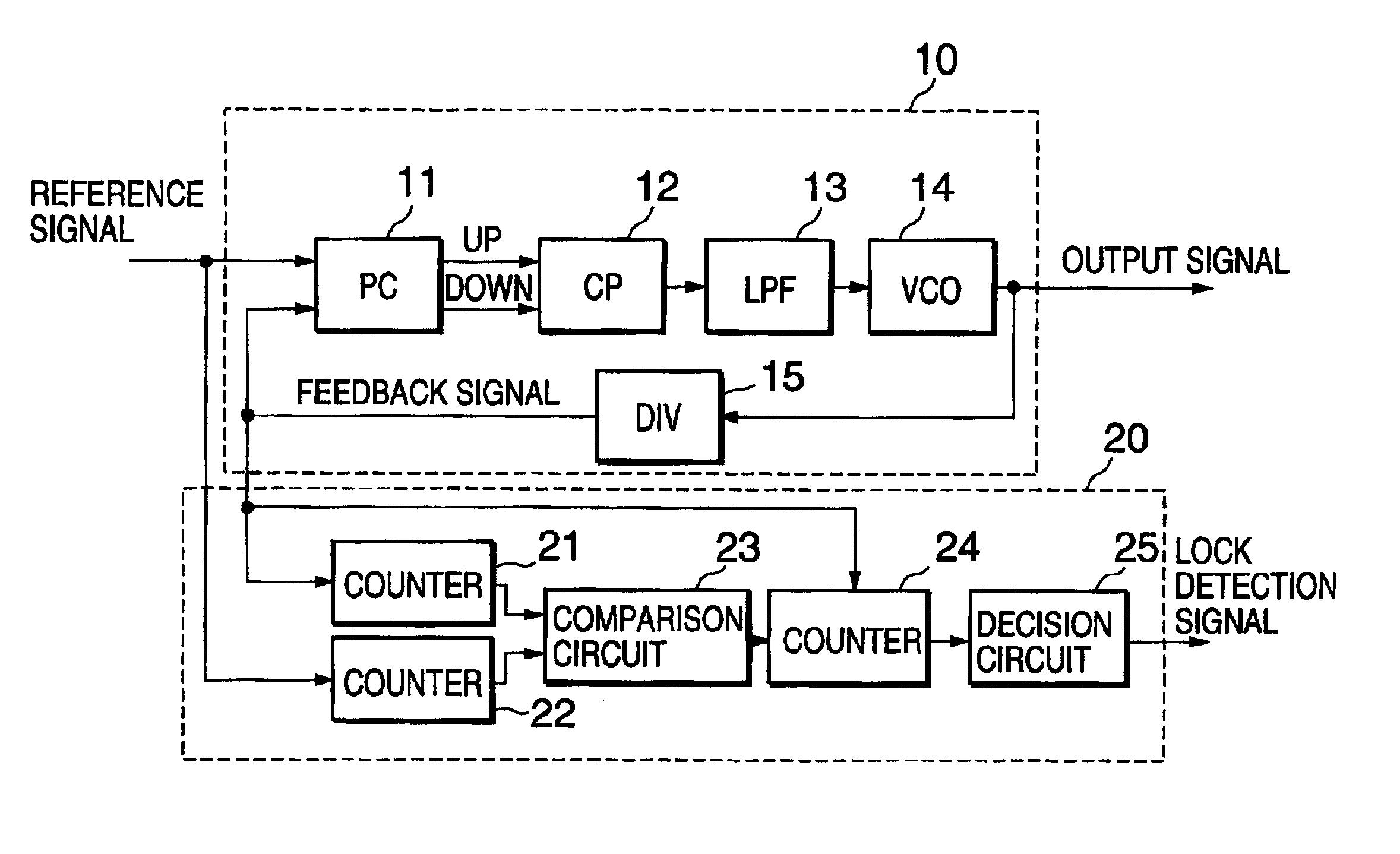
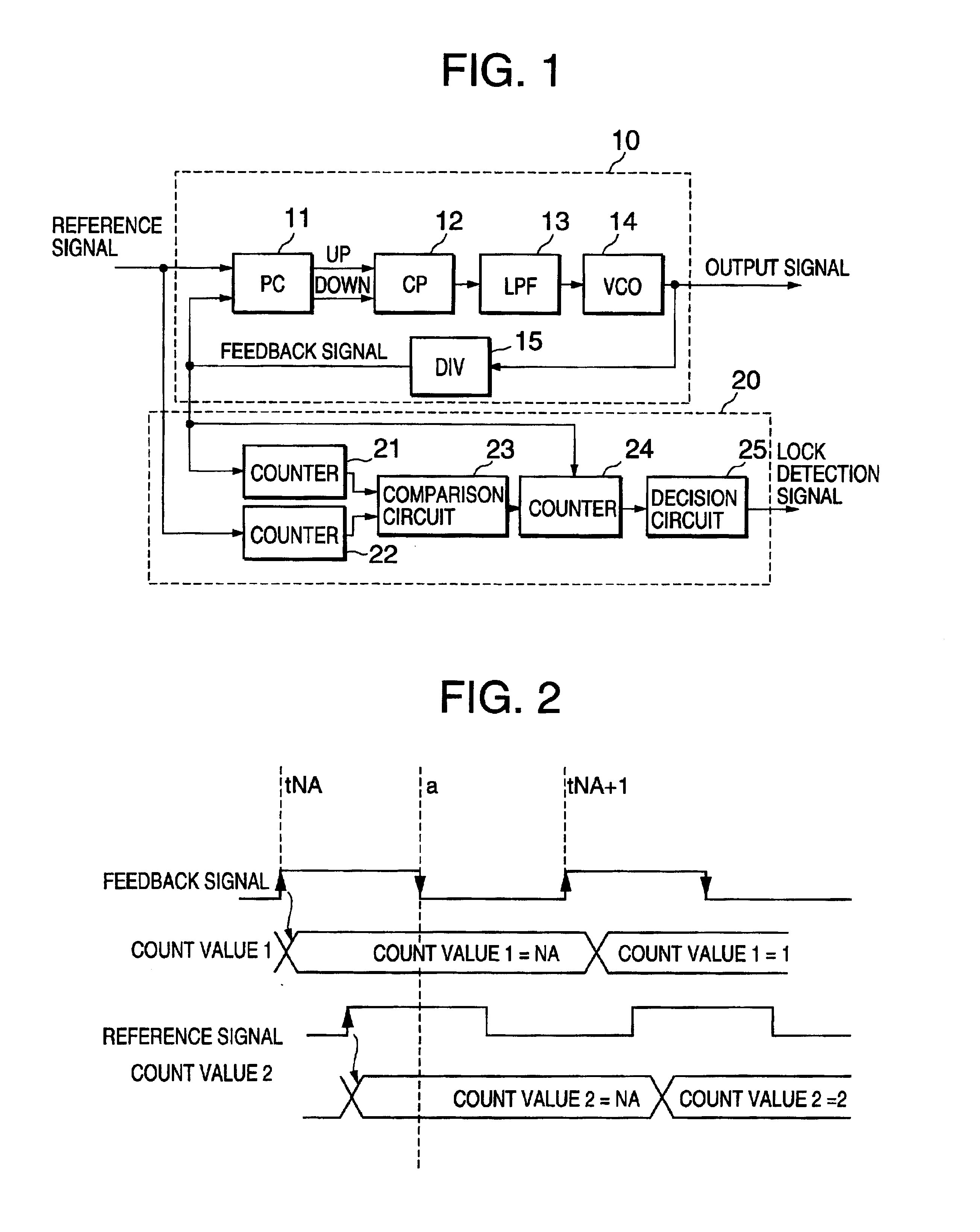
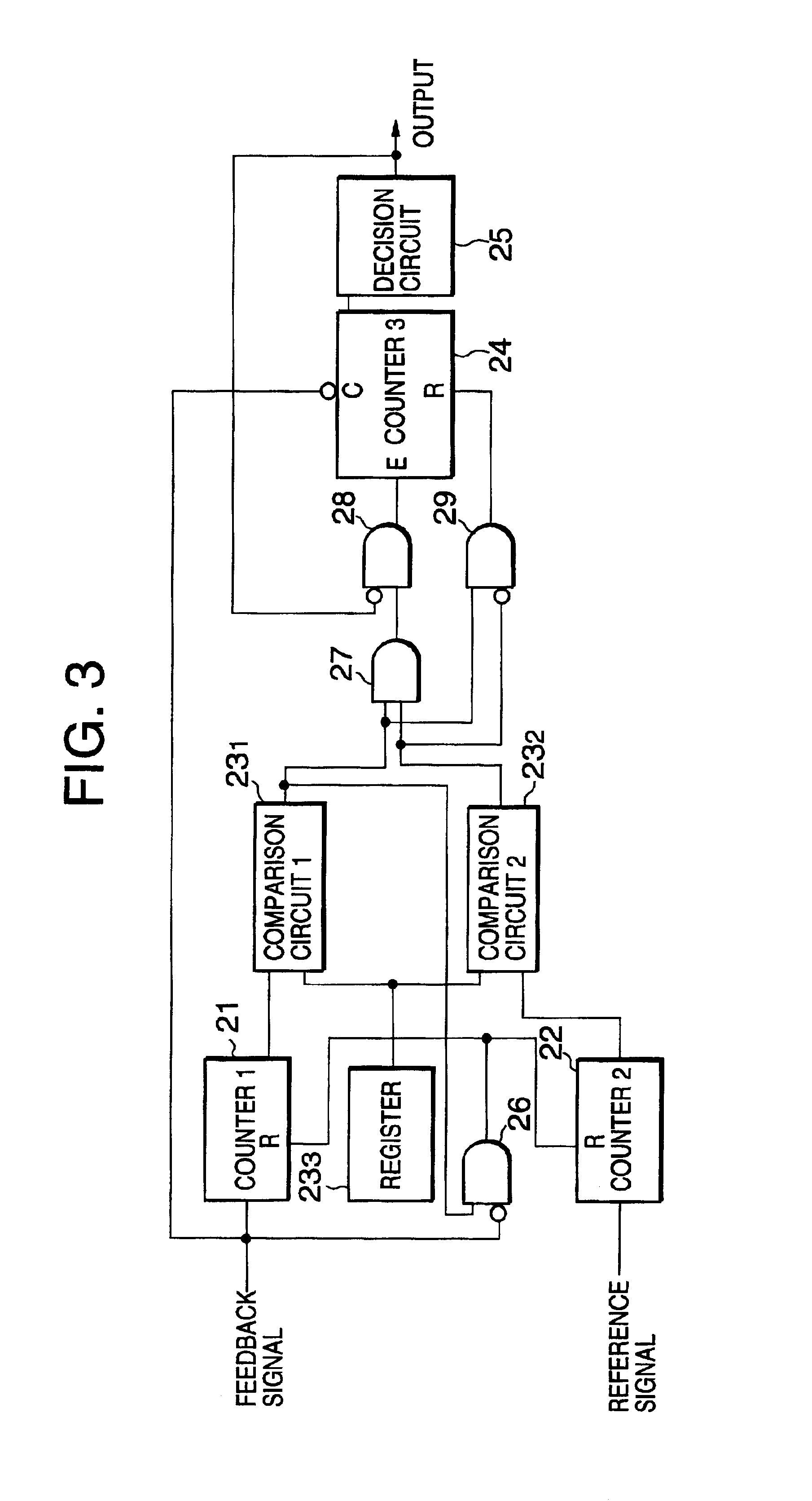
Lock detection circuit
a detection circuit and lock technology, applied in the direction of oscillator generators, pulse automatic control, electrical devices, etc., can solve the problems of longer time to detect the lock state or the unlock state than is required
- Summary
- Abstract
- Description
- Claims
- Application Information
AI Technical Summary
Benefits of technology
Problems solved by technology
Method used
Image

Examples
second embodiment
A second embodiment of the present invention will be described. FIG. 4 is a diagram showing the construction of a lock detection circuit of the present invention. In the second embodiment of the present invention, a first counter 21A, a second counter 22A and a third counter 24A count a predetermined set value and then output an output signal (1-bit signal) in a state showing coincidence (for example, High level). In such a construction, the construction including the first comparison circuit 231, the second comparison circuit 232 and the register 233 shown in FIG. 3 is unnecessary. As the output signal of the first counter 21A, the second counter 22A and the third counter 24A, an overflow signal outputted when the upper limit value (the set value) of the counter value is reached may be used.
A first AND circuit 26 functions as a counter reset circuit as in the above-described embodiment. When the first counter 21A counts the feedback signals by the value "NA", the output signal of t...
PUM
 Abstract
Description
Claims
Application Information