Fast response time, low power phase detector circuits, devices and systems incorporating the same, and associated methods

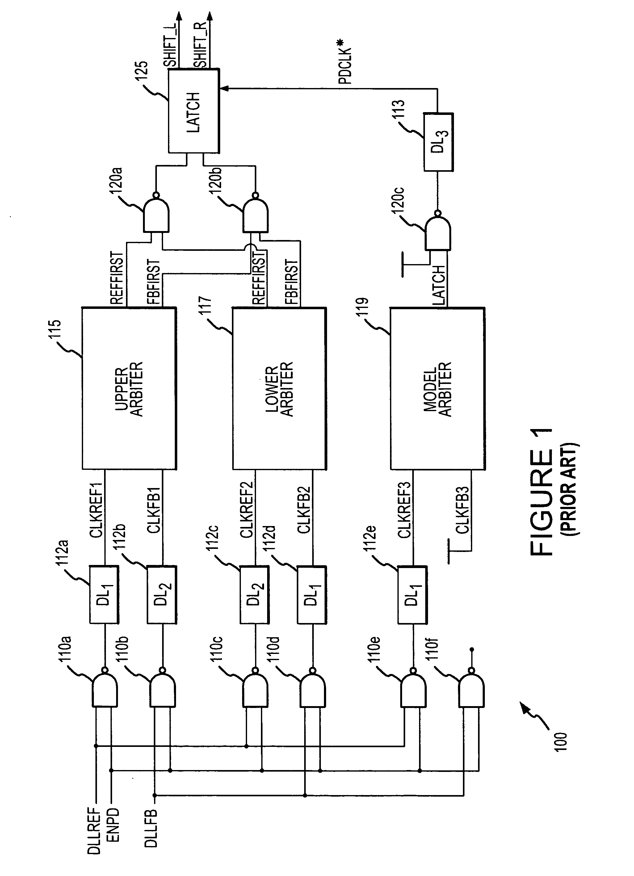
a phase detector and fast response technology, applied in the field of integrated circuits, can solve the problems of delay in taking action to correct phase errors in the loop, excessive total power and chip space, and excessive consumption of phase detector b>100/b>, so as to reduce power consumption and use of chip space, increase the overall likelihood of phase detector error, and high accuracy

Active Publication Date: 2008-06-05
MICRON TECH INC
View PDF63 Cites 33 Cited by
  • Summary
  • Abstract
  • Description
  • Claims
  • Application Information

AI Technical Summary

Benefits of technology

[0012]Other phase detectors have been designed using D-flip-flops instead of arbiters to reduce power consumption and use of chip space. However, because D-flip-flop have different setup and hold paths than of the arbiter-based systems, the phase detector has a tendency to exhibit phase bias, which may be regarded as a form of hysteresis. At high clock frequencies, the presence of phase bias or hysteresis in the phase detection increases the overall likelihood of phase detector error.
[0013]Therefore, there is a need for a highly accurate phase detector circuit operable to provide phase decisions without the effects of hysteresis or phase bias, and that does not rely on excessive delay lines or arbiters, thereby enabling a reduction in the overall size of the circuit and the consumption of power and chip space.

Problems solved by technology

Therefore, the phase detector 100 consumes excessive amounts of total power and chip space due to the multiple arbiters and delay lines included in the design.
This delay in providing the SHIFT_L and SHIFT_R signals slows the operation of the phase detector 100.
For example, if the phase detector 100 is used in a delay-lock loop (not shown), the slower operation of the phase detector 100 results in a delay in taking action to correct phase errors in the loop.
However, because D-flip-flop have different setup and hold paths than of the arbiter-based systems, the phase detector has a tendency to exhibit phase bias, which may be regarded as a form of hysteresis.
At high clock frequencies, the presence of phase bias or hysteresis in the phase detection increases the overall likelihood of phase detector error.

Method used


Image

  • Fast response time, low power phase detector circuits, devices and systems incorporating the same, and associated methods
  • Fast response time, low power phase detector circuits, devices and systems incorporating the same, and associated methods
  • Fast response time, low power phase detector circuits, devices and systems incorporating the same, and associated methods

Examples


Embodiment Construction

[0021]Embodiments of the present invention are directed to phase detection circuits capable of providing highly accurate phase detection, and methods of operation thereof as well as devices and systems including such circuits. Certain details are set forth below to provide a sufficient understanding of the invention. However, it will be clear to one skilled in the art that the invention may be practiced without these particular details. In other instances, well-known circuits, control signals, and timing protocols have not been shown in detail in order to avoid unnecessarily obscuring the invention.

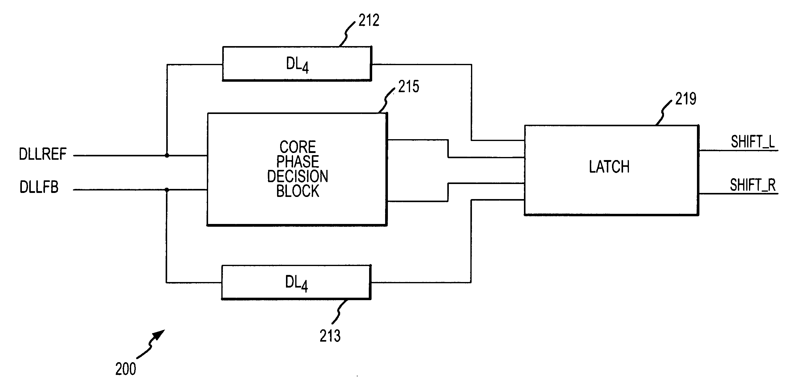
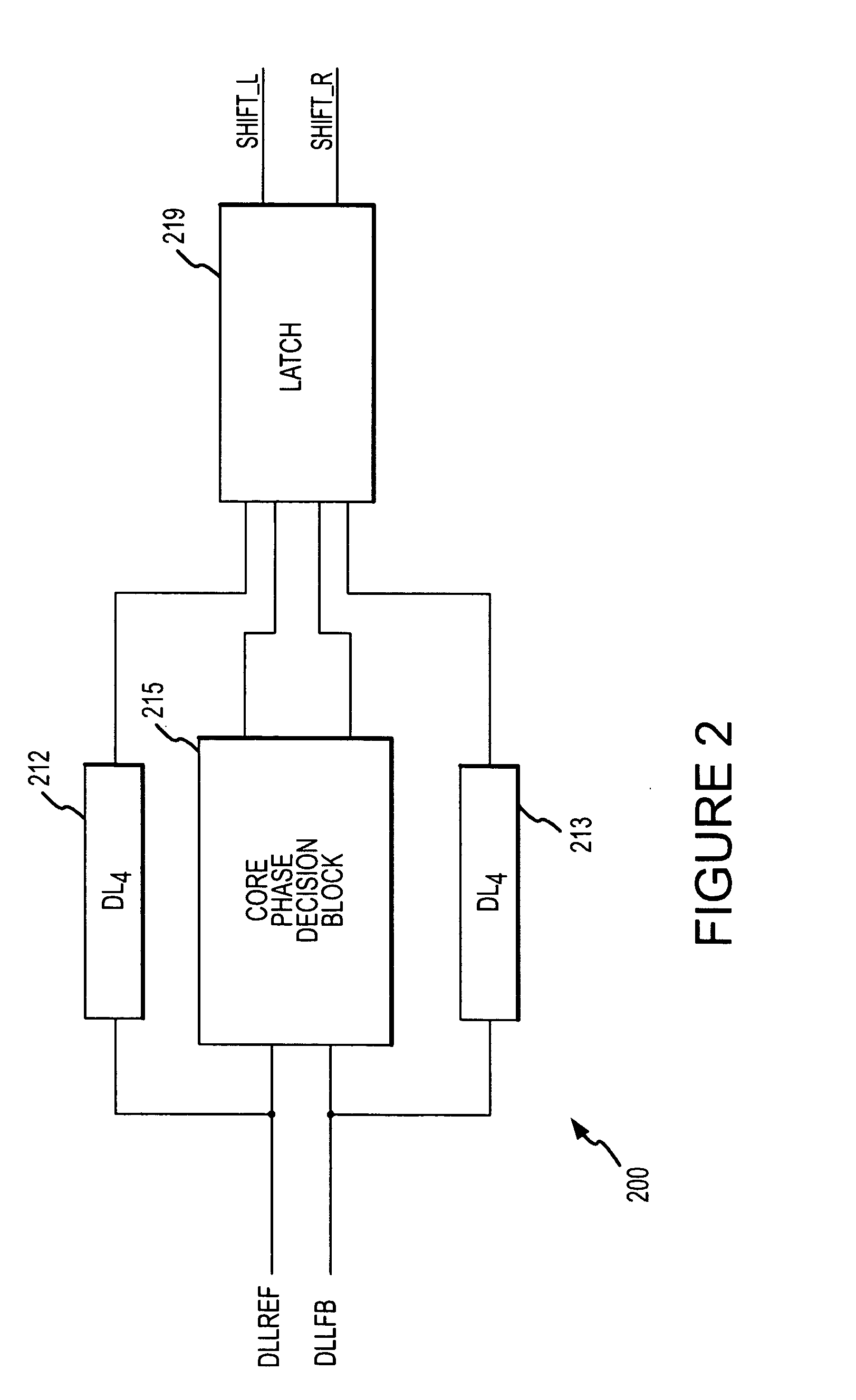
[0022]FIG. 2 shows an embodiment of a phase detector circuit 200 according to an embodiment of the invention. The phase detector circuit 200 receives two input clock signals DLLREF and DLLFB and, upon comparing the phase difference of the two input clock signals, the phase detector circuit 200 outputs one of two output clock signals SHIFT_R or SHIFT_L as HIGH. The SHIFT_R signal and the S...


PUM


Abstract

A circuit for quickly accomplishing highly accurate phase detection using low power is described. The circuit includes a phase decision circuit that receives two clock signals and detects the phase relationship between the two signals by determining which signal was received first. In response, the phase decision circuit generates respective logic signals to reflect the phase relationship determination. The circuit also includes a latch circuit that receives the logic signals from the phase decision circuit and holds the phase relationship determination of the circuit a predetermined time after a predetermined transition of both clock signals have occurred. Methods and systems are also disclosed.

Description

TECHNICAL FIELD[0001]Embodiments of the invention relate to integrated circuits, and more specifically to an apparatus and method for providing highly accurate phase detection to generate a control signal based on the phase relationship between two input clock signals.BACKGROUND OF THE INVENTION[0002]In synchronous integrated circuits, the integrated circuit is clocked by an external clock signal and performs operations at predetermined times relative to the rising and falling edges of the applied clock signal. Examples of synchronous integrated circuits include synchronous memory devices such as synchronous dynamic random access memories (“SDRAMs”), synchronous static random access memories (“SSRAMs”), and packetized memories like SLDRAMs and RDRAMs, and include other types of integrated circuits as well, such as microprocessors. The timing of signals external to a synchronous memory device is determined by the external clock signal, and operations within the memory device are typi...

Claims


Application Information

Patent Timeline
Patent Type & Authority Applications(United States)
IPC IPC(8): G11C8/18H03K5/125H03K5/14
CPCG11C8/12H03L7/085H03L7/0814H03K5/26G11C7/222G11C11/4076
Inventor GOMM, TYLERKWAK, JONGTAE
Owner MICRON TECH INC
Why Eureka
Try Eureka