Dynamic phase alignment of a clock and data signal using an adjustable clock delay line

a technology of dynamic phase alignment and clock delay, which is applied in the direction of time-delay network, digital transmission, pulse automatic control, etc., to achieve the effect of small delay and improved sampling resolution

Inactive Publication Date: 2006-04-25
SEMICON COMPONENTS IND LLC
View PDF5 Cites 31 Cited by
  • Summary
  • Abstract
  • Description
  • Claims
  • Application Information

AI Technical Summary

Benefits of technology

[0013]Sampling resolution is improved over the PLL-based dynamic phase adjustment circuit since the clock signal is delayed using delay elements, which can be made with relatively small delays. Furthermore, the circuit does not contain many circuit elements thereby allowing the dynamic phase adjustment circuit to be contained in a small area. This reduces the risk that the phase relationship between the various delayed clock signals will be lost.

Problems solved by technology

Furthermore, the circuit does not contain many circuit elements thereby allowing the dynamic phase adjustment circuit to be contained in a small area.

Method used


Image

  • Dynamic phase alignment of a clock and data signal using an adjustable clock delay line
  • Dynamic phase alignment of a clock and data signal using an adjustable clock delay line
  • Dynamic phase alignment of a clock and data signal using an adjustable clock delay line

Examples


Embodiment Construction

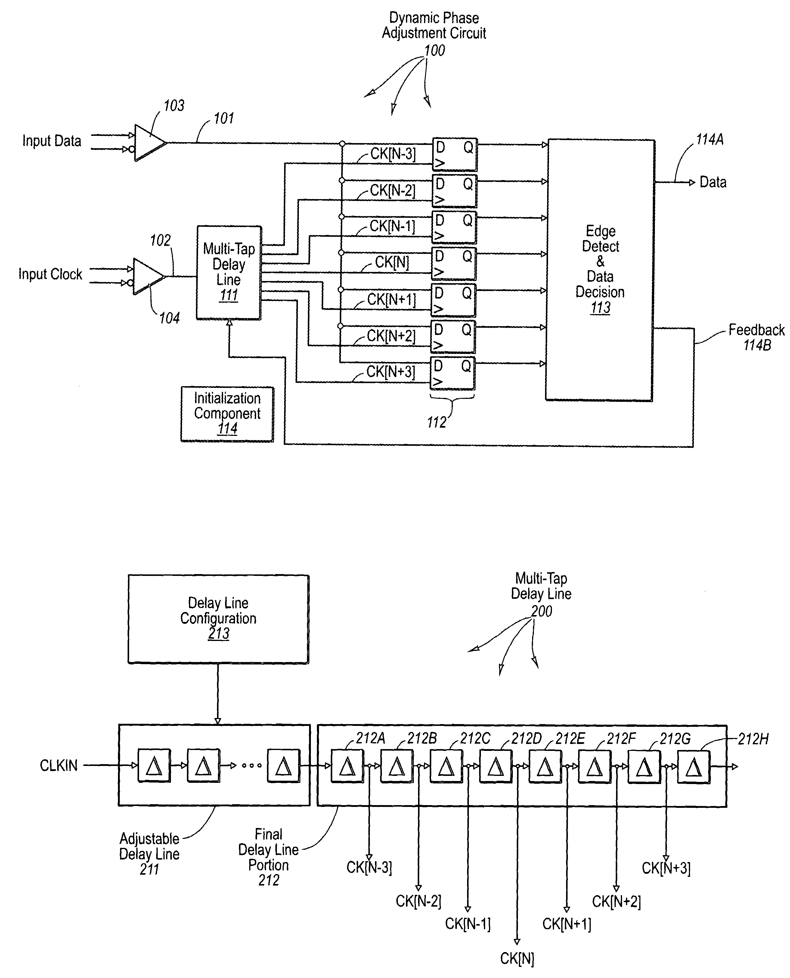
[0023]The principles of the present invention relate to a dynamic phase adjustment circuit. Dynamic phase adjustment circuits serve to keep the phase of the clock and data signals synchronized during source synchronous data transfer so that the data may be properly sampled and interpreted at the receiving side. The dynamic phase adjustment circuit can significantly improve the sampling resolution as compared to the PLL-based dynamic phase adjustment circuit described above, while being potentially far less complex than the multi-tap delay line dynamic phase adjustment circuit also described above.

[0024]FIG. 1 illustrates a dynamic phase adjustment circuit 100 in accordance with the principles of the present invention. The dynamic phase adjustment circuit 100 includes a data input terminal 101 for receiving input data during operation, and a clock input terminal 102 for receiving clock signals during operation. When the data signal is transmitted in differential form, a differential ...


PUM


Abstract

A dynamic phase adjustment circuit that includes a multi-tap delay line that receives a clock input signal. The multi-tap delay line includes an initial portion that is adjustable, and final portion after the adjustable portion. A number of registers receive the same data. However, the clock signal that causes the registers to sample is received from a corresponding delay element in the final portion of the multi-tap delay line. An edge detect and data decision circuit receives the sampled data values from each of the registers. Sampling resolution is improved over the PLL-based dynamic phase adjustment circuit since the clock signal is delayed using delay elements, which can be made with relatively small delays. Furthermore, the circuit does not contain excessive circuit elements thereby allowing the dynamic phase adjustment circuit to be contained in a small area.

Description

BACKGROUND OF THE INVENTION[0001]1. The Field of the Invention[0002]The present invention relates generally to mechanisms for synchronous data transfer between two circuits. More specifically, the present invention relates to dynamic phase alignment of a clock and data signal using an adjustable clock delay line.[0003]2. Background and Relevant Art[0004]Electronic circuitry has become critical to the functionality of many common devices and systems. In order to accomplish a desired function, it is often desirable for one circuit to communicate with another. The communicating circuits may be on the same chip or even on different chips. Sometimes, the data communicated between the circuits has validity implied from the timing of the data relative to another signal such as a clock. This type of data transfer is often referred to as synchronous data transfer.[0005]In chip-to-chip source synchronous data transfer, a clock signal and a data signal are transmitted from the source circuit. ...

Claims


Application Information

Patent Timeline
Patent Type & Authority Patents(United States)
IPC IPC(8): H03H11/26
CPCH04L7/0337H03L7/0814
Inventor MO, SHANBROWN, JAMES R.MOSHER, RICHARD A.KIRK, ROBERT S.
Owner SEMICON COMPONENTS IND LLC
Why Eureka
Try Eureka