Multipole electrical connector

Inactive Publication Date: 2004-09-28
FISCHER CONNECTORS HLDG
View PDF8 Cites 7 Cited by
  • Summary
  • Abstract
  • Description
  • Claims
  • Application Information

AI Technical Summary

Benefits of technology

According to a preferred embodiment of the invention, the width of the protrusion is appreciably greater than that of the recess so as to make the ground contact more effective.
According to another advantageous embodiment of the invention, the protrusion has a slot arranged along th

Problems solved by technology

With connectors of the prior art as described above, the ground contact via the metal guides cannot be achieved because the clearance needed for them to have correct mechanical operation dictates a certain distance between the edges of the guides.
This problem is particularly pronounced when the casing of th

Method used


Image

  • Multipole electrical connector
  • Multipole electrical connector
  • Multipole electrical connector

Examples


Example

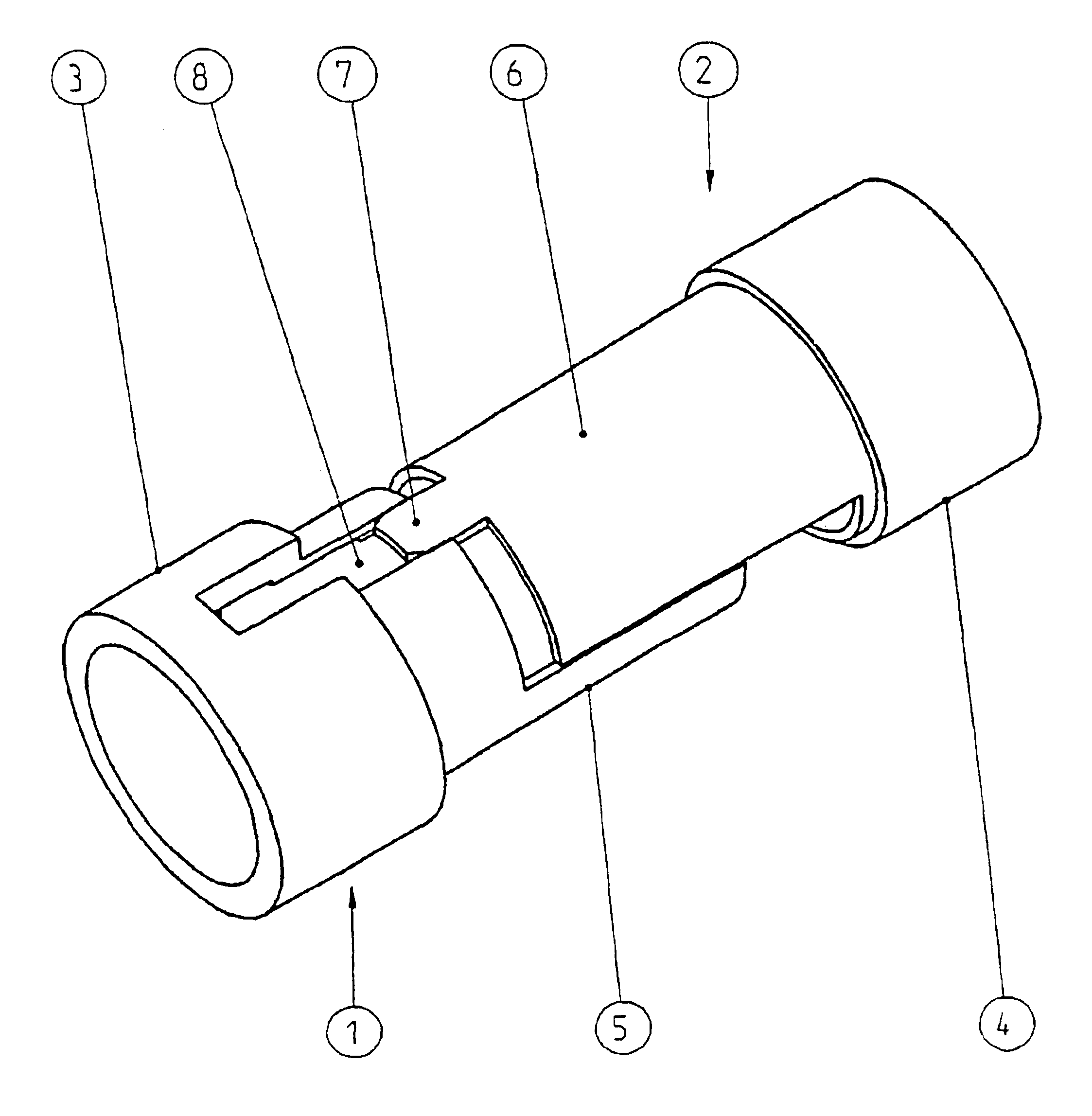
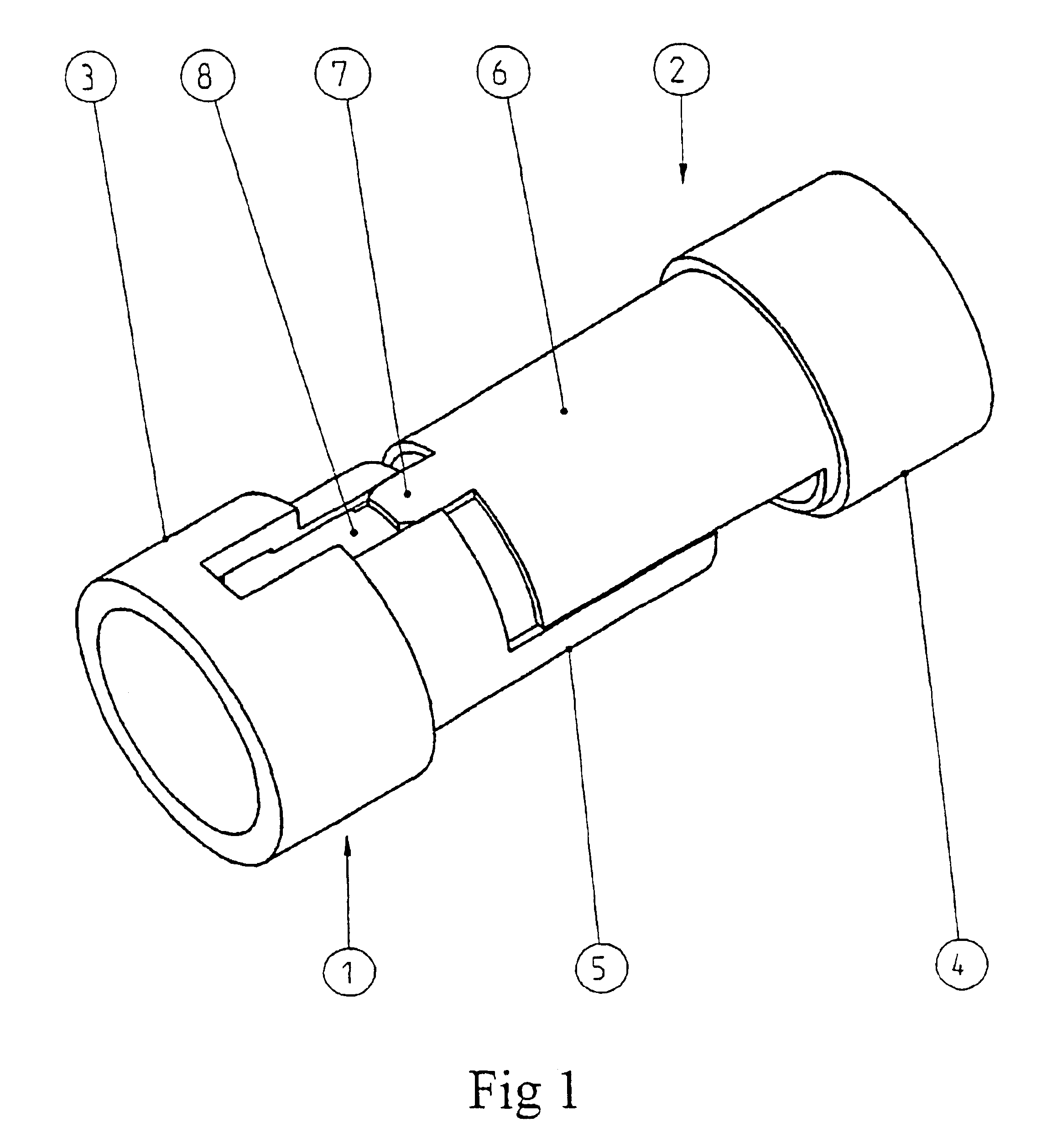
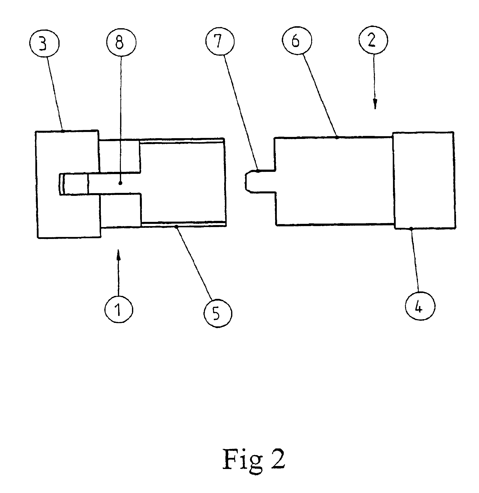
With a view to simplifying the description of the invention, the following figures depict only the "heart" of the invention, namely a pair of metal guides 1, 2. The casing of the connector, which casing surrounds the guides, and the male and female blocks which are placed inside the guides, are not illustrated.

Each guide 1, 2 is made up of a proximal part 3, 4 of cylindrical shape and of a distal part 5, 6 representing a semi-cylinder.

Once the connector has been connected, the distal parts 5, 6 become superimposed on one another and form a cylinder. The free end of the distal part 6 of one of the guides 2 has a protrusion 7 located mid-way between the edges of the semi-cylinder that makes up the distal part 6 and which is arranged along the main axis of the guides 1, 2.

The free end of the proximal part 3 of the other guide 1 comprises a recess 8 the shape of which is such that the protrusion 7 can be housed firmly therein. In order to improve the electrical contact at the protrusion...


PUM


Abstract

The invention relates to an electrical connector comprising a male contact block and a female contact block. Each of said blocks is mounted in a metallic guide (1, 2) consisting of a cylindrical proximal part (3, 4) and a distal part (5, 6) representing a cylindrical portion, both distal parts (5, 6) being of a complementary nature so as to form a cylinder when the connector is closed. The inventive electrical connector is characterised in that the proximal (3, 4) or distal (5, 6) part of one of the guides (1, 2) comprises a projecting part (7) which is housed in an opening (8) in the distal (6, 5) or proximal (4, 3) part of the other guide (2, 1).

Description

BACKGROUND OF THE SUMMARY OF THE INVENTIONThe present invention relates to the field of electrical connectors and in particular the field of multipole electrical connectors. It relates more specifically to an electrical connector comprising a male contact block and a female contact block, each block being mounted in a metal guide comprising at least a portion of a cylinder.Electrical connectors of the aforementioned type are known (see, for example, the applicant company's general catalog issued in 1997). Each metal guide consist of a proximal part of cylindrical shape and of a distal part representing a portion of the cylinder, for example a semi-cylinder, the two distal parts of each block complementing each other so as to form a cylinder when the connector is connected.The guides as described above facilitate the guidance and positioning of the male block with respect to the female block; this is particularly important in the case of multipole connectors where it is absolutely es...

Claims


Application Information

Patent Timeline
IPC IPC(8): H01R13/658H01R13/642H01R13/648H01R13/639
CPCH01R13/642H01R13/65802H01R13/6582
Inventor REICHARZ, ARMIN
Owner FISCHER CONNECTORS HLDG
Why Eureka
Try Eureka