Self-adjusting deflection controlled roll

Inactive Publication Date: 2004-09-28
VOITH PATENT GMBH
View PDF14 Cites 4 Cited by
  • Summary
  • Abstract
  • Description
  • Claims
  • Application Information

AI Technical Summary

Benefits of technology

The piston in cylinder arrangement can directly contact the inner side of the bearing sleeve or a shallow side of an intermediate member arranged between the carrier and the bearing sleeve. In the latter case, the advantage results that the piston does not have to be matched to the curved inner side of the guide sleeve.
Substantial arrangement advantages result with respect to the previously usual floating roll with an outer pressing system via levers. These include, for example, a simpler and more cost favorable roll stool, a simpler felt and roll replacement, a more compact design despite the larger roll (more free space for the arrangement of scrapers, spray tubes, suction bladders, etc.), planning benefits for conversion work with low construction space and a simple design which is service friendly, operator friendly and safe in operation.

Problems solved by technology

It is thus excluded that torques arise in operation which can act disadvantageously on the toothed engagement of the drive toothed arrangement so that the toothed flanks can ideally contact one another within the framework of the bearing clearances in the main bearings.

Method used


Image

  • Self-adjusting deflection controlled roll
  • Self-adjusting deflection controlled roll
  • Self-adjusting deflection controlled roll

Examples


Embodiment Construction

The particulars shown herein are by way of example and for purposes of illustrative discussion of the embodiments of the present invention only and are presented in the cause of providing what is believed to be the most useful and readily understood description of the principles and conceptual aspects of the present invention. In this regard, no attempt is made to show structural details of the present invention in more detail than is necessary for the fundamental understanding of the present invention, the description taken with the drawings making apparent to those skilled in the art how the several forms of the present invention may be embodied in practice.

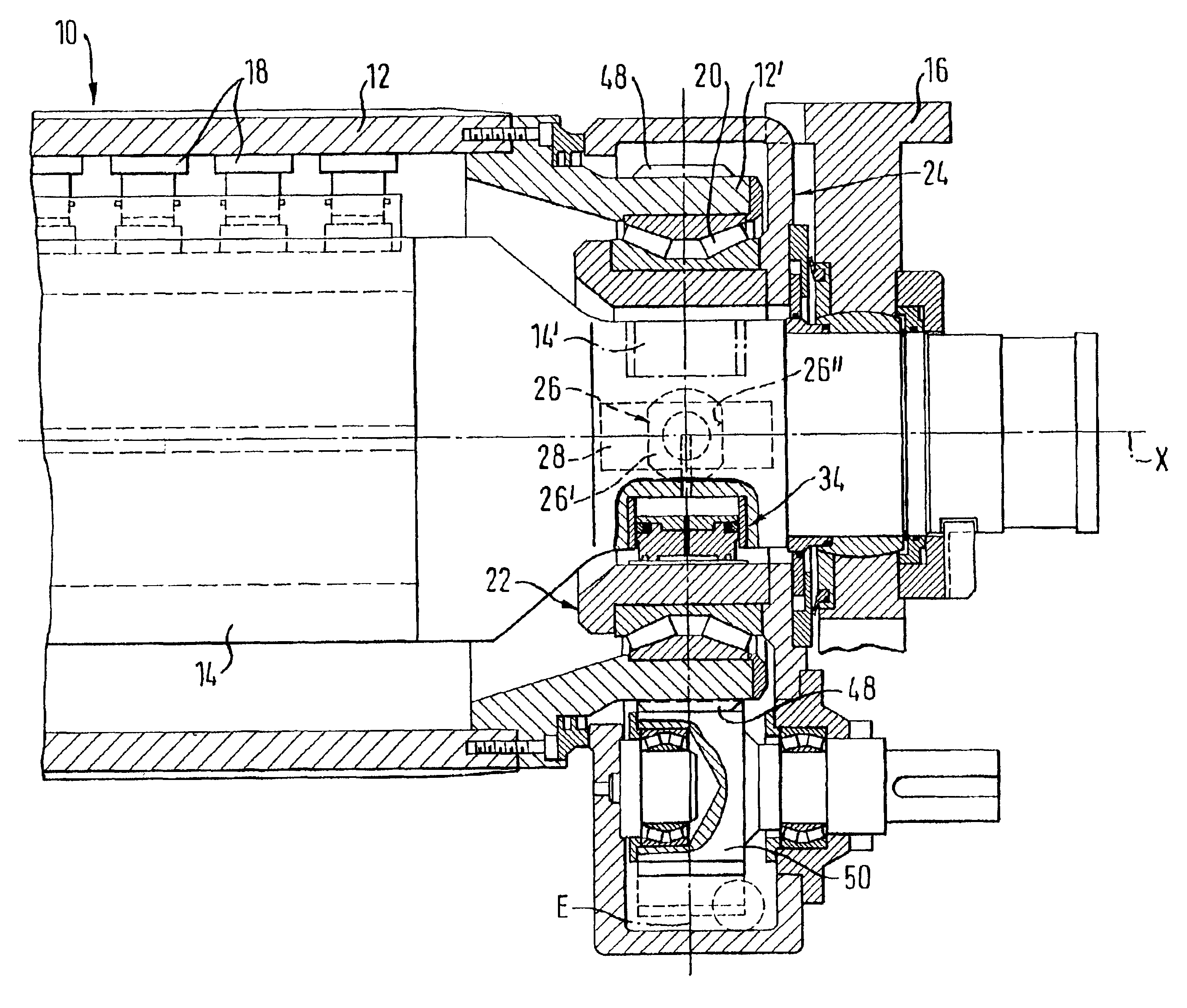
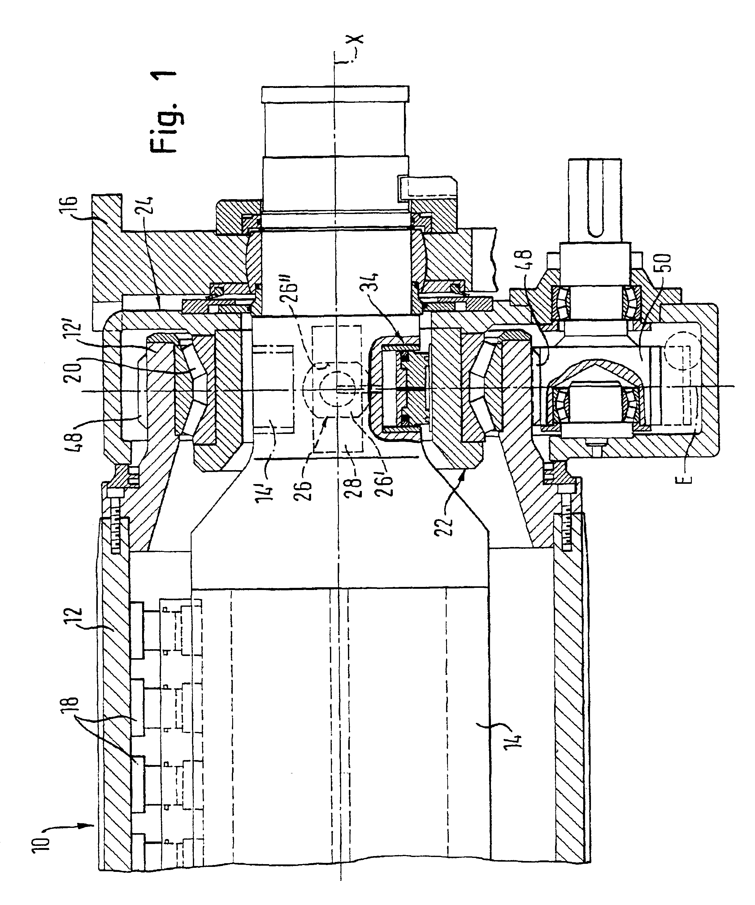
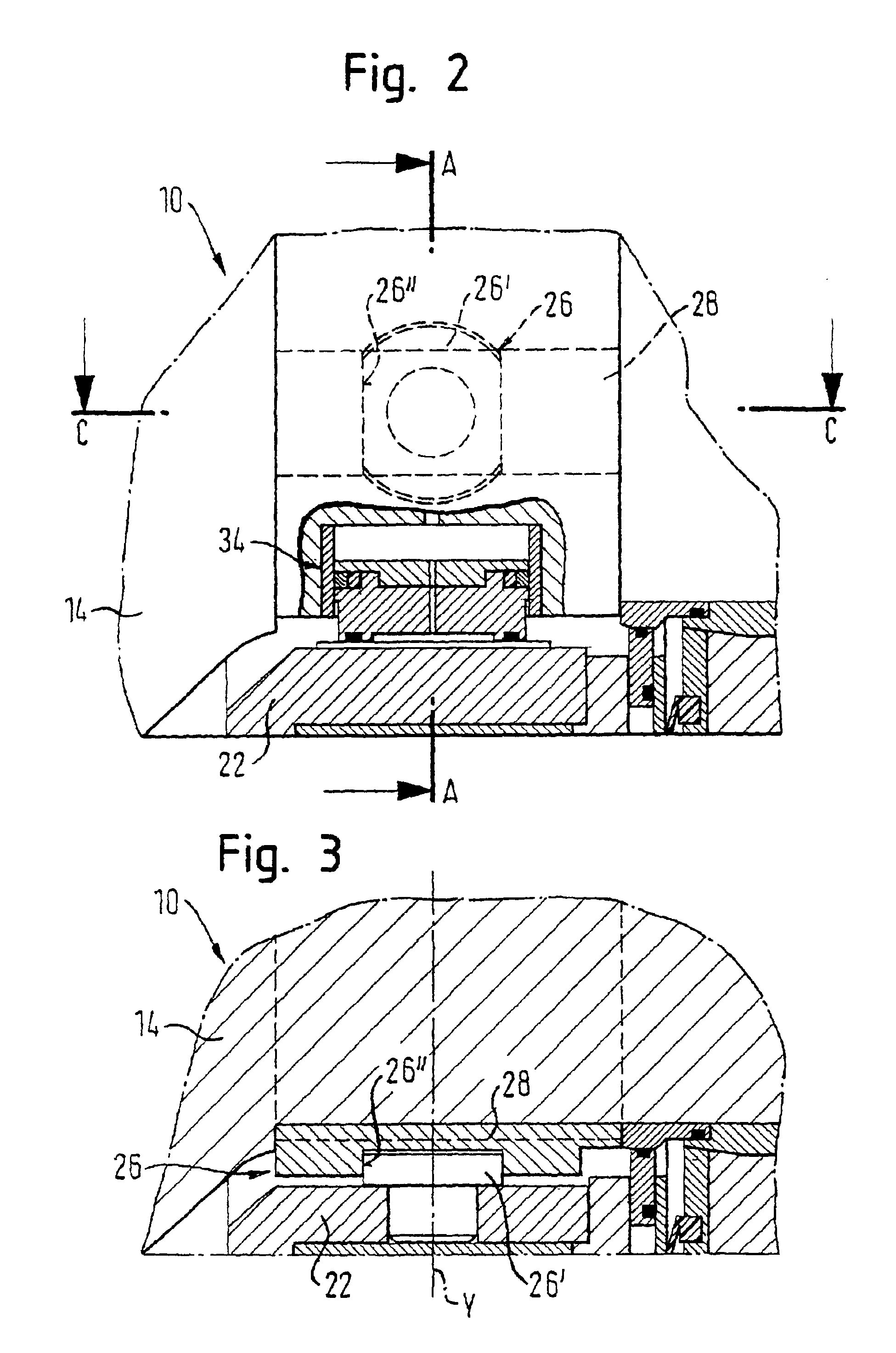
FIGS. 1 to 6 show a self-adjusting deflection controlled roll 10 in a purely schematic representation.

This deflection controlled roll 10 includes a rotating roll jacket 12 and a carrier 14 passing through it axially.

The carrier 14 is held rotationally fixedly at its sides in racks 16, with only the drive-side rack 16 being show...


PUM

PropertyMeasurementUnit
widthaaaaaaaaaa
machine speedsaaaaaaaaaa

Abstract

A self-adjusting deflection controlled roll comprises a rotating roll jacket, a carrier passing axially through the roll jacket and held rotationally fixedly at its end in racks and at least one supporting member arranged at the carrier and exerting a support force on the inner side of the roll jacket in a pressing plane, with at least one axial end of the roll jacket or an axial continuation associated with it being rotationally mounted by at least one bearing on a non-rotating axial bearing sleeve of a bearing housing secured against rotation extending into the region between the roll jacket or the axial continuation and the carrier, said bearing housing being freely movable relative to the carrier substantially in the pressing plane perpendicular to the roll axis. The roll jacket is radially supported via the axial bearing sleeve of a respective bearing housing transversely to the pressing force plane and is axially fixed at the carrier at an axial end via guide means provided radially between the bearing sleeve of the relevant bearing housing and the carrier and permitting both a tilting moving and a movement of the bearing sleeve relative to the carrier substantially in the pressing plane perpendicular to the roll axis.

Description

The present application claims priority under 35 U.S.C. .sctn.119 of German Patent Application No. 101 10 695.5 filed on Mar. 6, 2001, the disclosure of which is expressly incorporated by reference herein in its entirety.1. Field of the InventionThe invention relates to a self-adjusting deflection controlled roll comprising a rotating roll jacket, a carrier which passes axially through the roll jacket and which is rotationally fixedly held at its ends in racks, and at least one support member arranged at the carrier and exerting a support force on the inner side of the roll jacket in a pressing plane, with at least one axial end of the roll jacket or an axial continuation associated with this being rotatably mounted by at least one bearing on a non-rotating axial bearing sleeve of a bearing housing secured against rotation extending into the region between the roll jacket or the axial continuation and the carrier, said bearing housing being freely movable relative to the carrier sub...

Claims


Application Information

Patent Timeline
Patent Type & Authority Patents(United States)
IPC IPC(8): D21G1/00D21G1/02F16C23/00F16C23/08F16C13/00F16C13/02
CPCD21G1/022D21G1/0226F16C13/02F16C13/028F16C23/08
Inventor MESCHENMOSER, ANDREAS
Owner VOITH PATENT GMBH
Why Eureka
Try Eureka