
Membrane switch, key switch using membrane switch, keyboard having key switches, and personal computer having keyboard

a membrane switch and key switch technology, applied in contact mechanisms, electrical apparatus casings/cabinets/drawers, instruments, etc., can solve the problems of membrane switch no longer performing a switching function, difficult to perform a stable switching operation, and inability to restore the original sta

Inactive Publication Date: 2004-09-28
BROTHER KOGYO KK
View PDF11 Cites 61 Cited by
  • Summary
  • Abstract
  • Description
  • Claims
  • Application Information

AI Technical Summary

Benefits of technology

The solution enables reliable switching operations with maintained resilient restoring force, stable key operability, and secure adhesion without bubbles, enhancing the durability and performance of membrane switches and key switches.

Problems solved by technology

When the deformed state of the switch portion by pushing in the upper membrane sheet is left as it is for a long period, the switch portion is subjected to the plastic deformation and maintains the deformed state by pushing and it is no more possible to restore the original state.
In such a case, the upper electrode of the upper membrane sheet and the lower electrode of the lower membrane sheet assume a switch-on state in which they are always in contact with each other and hence, there arises a drawback that the membrane switch no more performs a switching function.
In such a membrane switch, when the upper membrane sheet is pushed directly using a finger, although a pushing portion is formed on an upper surface of the upper membrane sheet by printing or the like for facilitating finding of the pushing portion with eyes, it is not always possible to push an appropriate position of the pushing portion with the finger and hence, it is difficult to perform a stable switching operation.
Further, when the flat upper membrane sheet is indirectly pushed by way of a so-called rubber spring or a key top which is generally known, there exist the irregularities in the accuracy of size attributed to manufacturing thereof and such irregularities in the accuracy of size directly affects influences on the pushing characteristics of the membrane switch.
In such a case, it is difficult to perform the stable switching operation in the manner as the above-mentioned case.
Accordingly, the membrane switch per se has large resiliency and hence, handling of the membrane switch is cumbersome and difficult in many case.
However, since the membrane switch has the large resiliency as mentioned previously, it is difficult to handle the membrane switch in a flat state.
Accordingly, in fixing the membrane switch to the support plate or the like by adhesion, there exists a considerable fear that bubbles remain between the lower membrane sheet and the support plate or the like.
When the bubbles remain between the lower membrane sheet and an adhering surface of the support plate or the like, irregularities are formed on a surface of the membrane switch thus giving rise to an unstable switching operation.
This rubber sheet is liable to easily receive the influence attributed to the use environment such as temperature, humidity or the like and hence, the rubber sheet is degraded in a relatively short period and exhibits poor durability.
When the rubber sheet is always held in such an elastically deformed state, along with the fact that the rubber sheet exhibits poor durability, the rubber sheet is subjected to a permanent deformation and does not return to the original state (state in which the rubber sheet has an original elastic force).
Accordingly, the height of the key top at the non-pushdown position becomes inevitably large and hence, it is extremely difficult to reduce the thickness of the key switch.

Method used


Image

  • Membrane switch, key switch using membrane switch, keyboard having key switches, and personal computer having keyboard
  • Membrane switch, key switch using membrane switch, keyboard having key switches, and personal computer having keyboard
  • Membrane switch, key switch using membrane switch, keyboard having key switches, and personal computer having keyboard

Examples


first embodiment

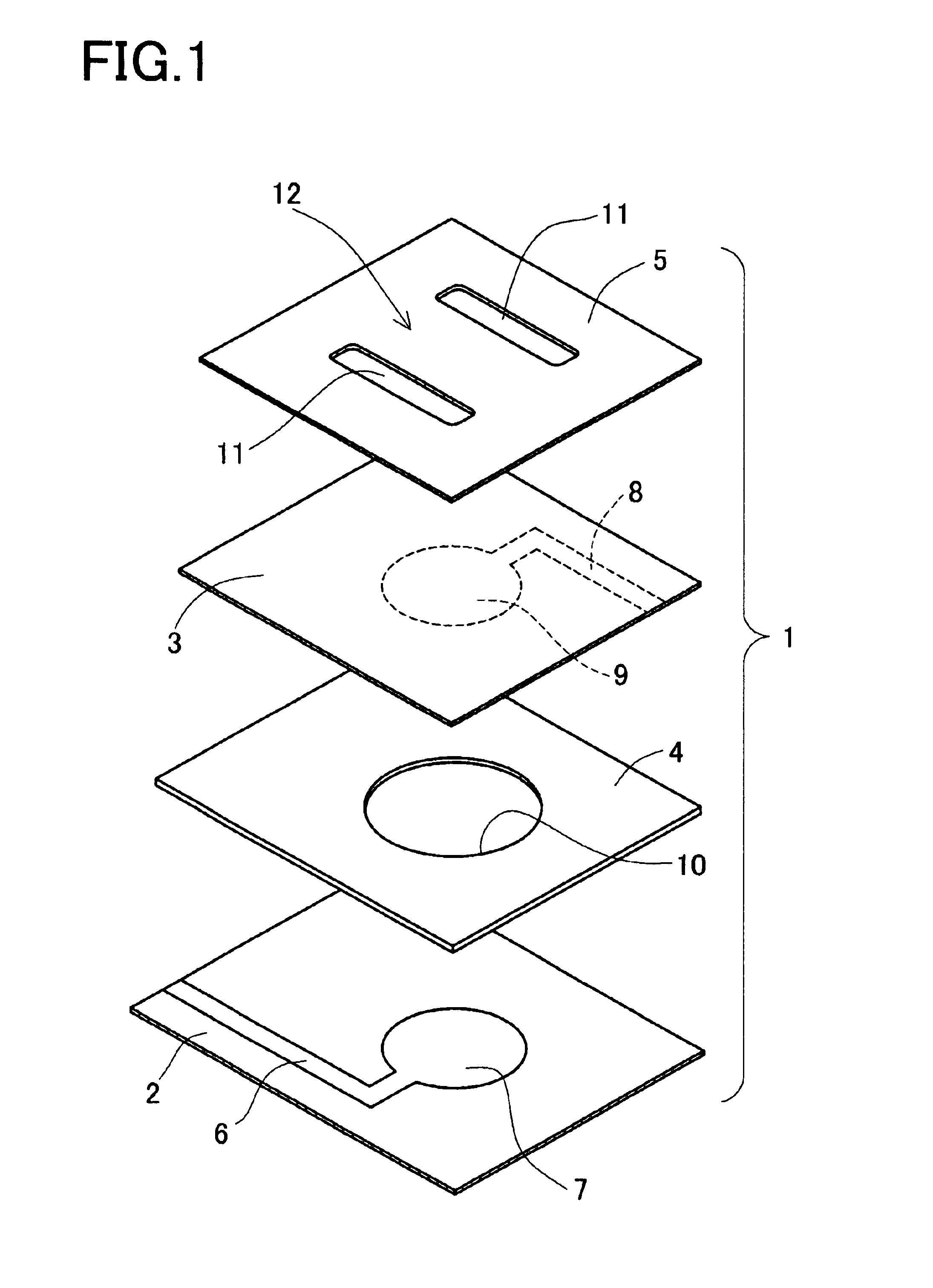
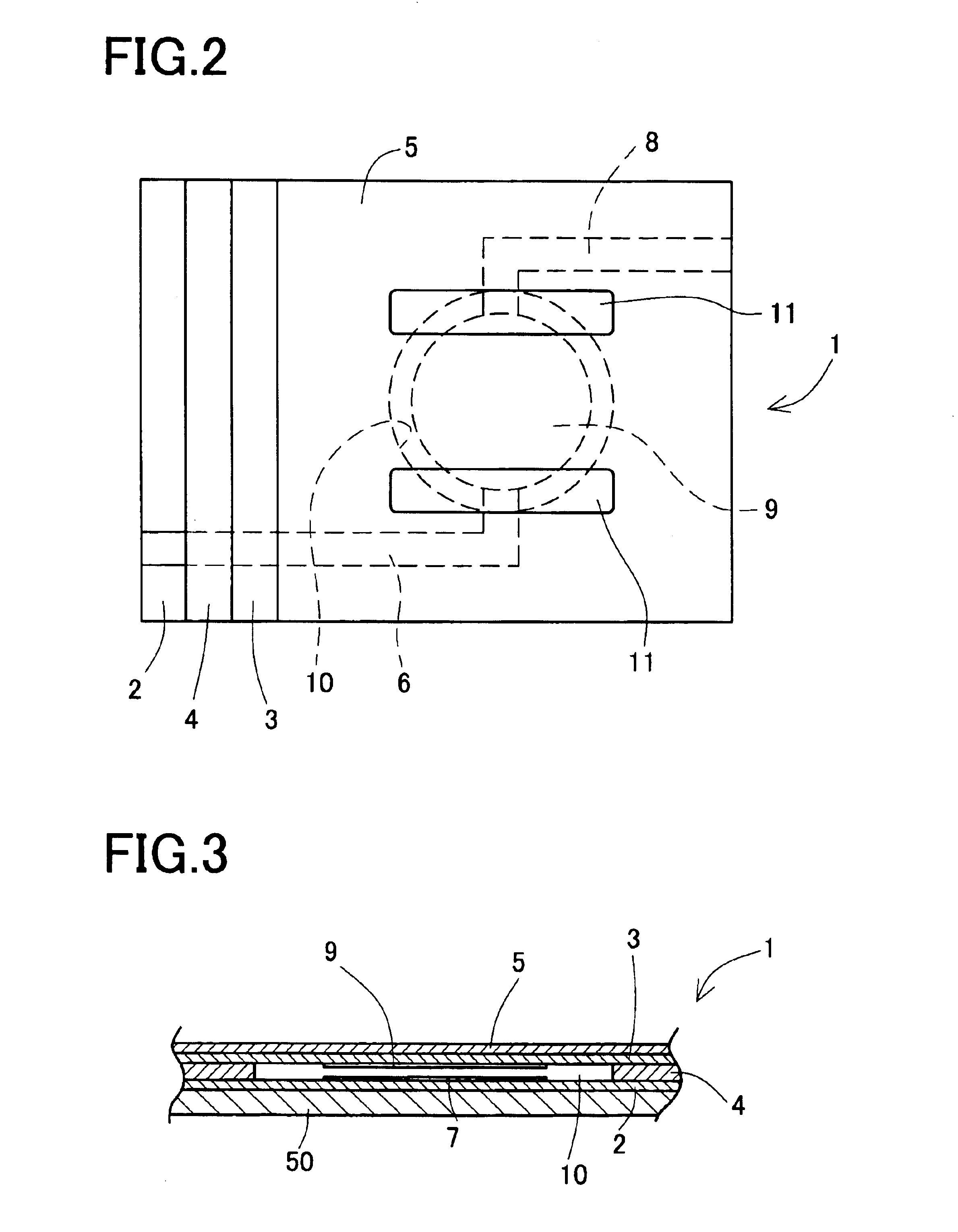
Subsequently, a membrane switch which is used in a key switch attached to the keyboard 105 of the above-mentioned notebook type personal computer 101 is explained in conjunction with FIG. 1 to FIG. 3. Here, FIG. 1 is an exploded perspective view showing a portion of the membrane switch in an exploded manner, FIG. 2 is a plan view showing a portion of the membrane switch, and FIG. 3 is a cross-sectional side view of the membrane switch.

In FIG. 1, the membrane switch 1 is basically constituted of a lower membrane sheet 2, an upper membrane sheet 3, a spacer sheet 4 which is interposed between the lower membrane sheet 2 and the upper membrane sheet 3, and a spring sheet 5 which is laminated to the upper membrane sheet 3. The membrane switch 1 is, as shown in FIG. 3, supported on a support plate 50.

Here, the lower membrane sheet 2 is formed of a film sheet made of polyethylene terephthalate (hereinafter abbreviated as "PET) and a lower switch electrode 7 which is connected to a circuit...

second embodiment

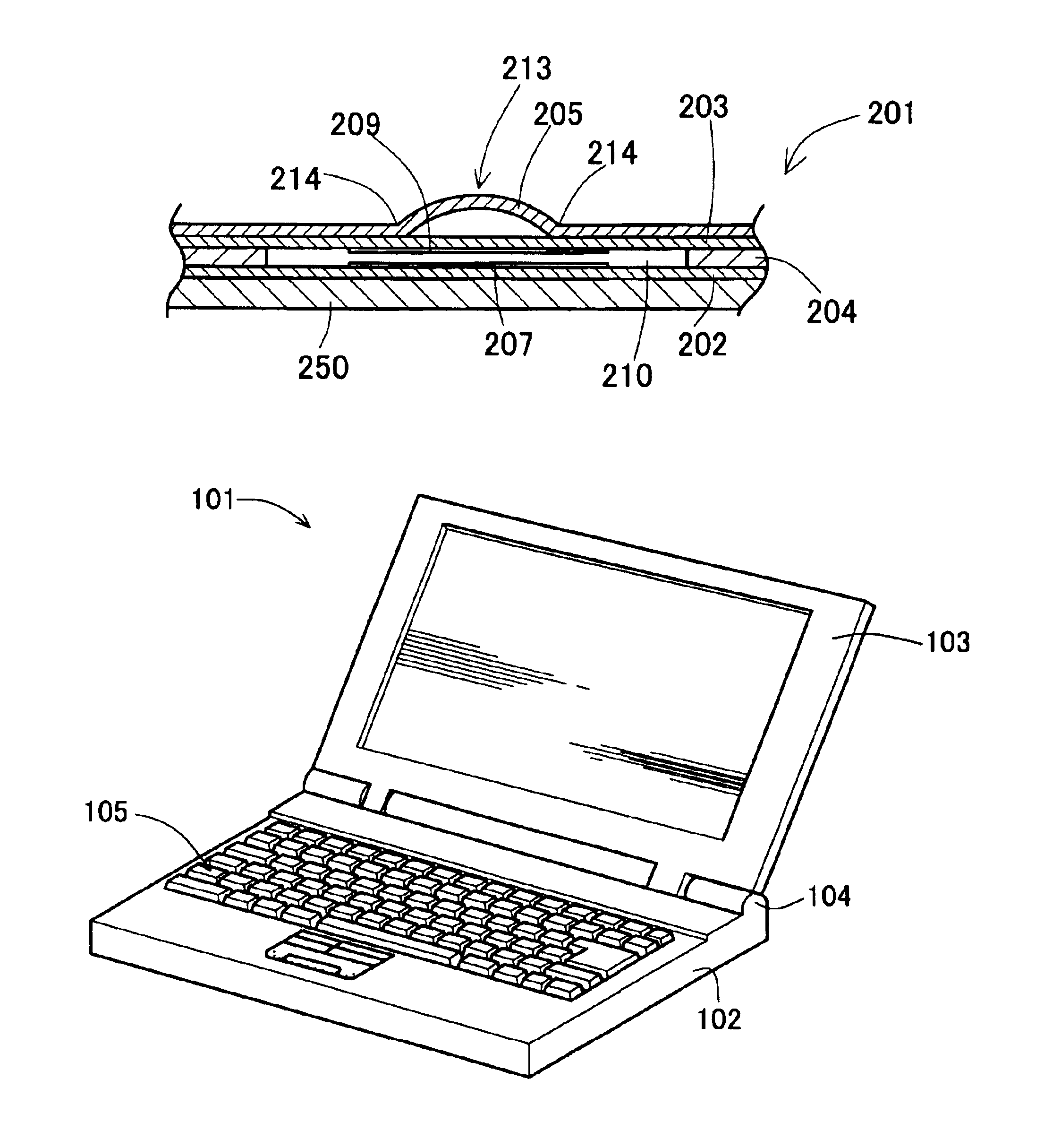
In the membrane switch 201 according to the above-mentioned second embodiment, the spring sheet 205 formed of the thin metal plate is arranged above the upper membrane sheet 203 and the semispherical bulging portion 213 is formed on the spring sheet 205 corresponding to the upper electrode 209. Accordingly, when the semispherical bulging portion 213 is pushed down using the finger, the rubber spring, the key top or the like at the time of operating the switch, the upper membrane sheet 203 is pushed by way of the connecting portion 214 between the bulging portion 213 and the spring sheet 205 disposed around the bulging portion 213 and hence, the upper electrode 209 of the upper membrane sheet 203 is brought into contact with the lower electrode 207 of the lower membrane sheet 202 through the switching hole 210 formed in the spacer sheet 204 whereby the switching operation is performed. Here, since the upper membrane sheet 203 is pushed by the connecting portion 214 between the bulgin...

third embodiment

In the membrane switch 201 according to the above-mentioned third embodiment, the spring sheet 205 formed of the thin metal plate is arranged above the upper membrane sheet 203 and a pair of resilient cut-and-raised lugs 215 are formed in the spring sheet 205 corresponding to the upper electrode 209. Accordingly, when the respective resilient cut-and-raised lugs 215 are pushed by a finger, a rubber spring, a key top or the like at the time of performing the switching operation, the upper membrane sheet 203 is pushed byway of the connecting portions 217 between the resilient cut-and-raised lugs 215 and the spring sheet 205 and hence, the upper electrode 209 of the upper membrane sheet 203 is brought into contact with the lower electrode 207 of the lower membrane sheet 202 through the switching hole 210 formed in the spacer sheet 204 whereby the switching operation is performed. Here, since the upper membrane sheet 203 is pushed by the connecting portion 217 between resilient cut-and-...


PUM


Abstract

A membrane switch is constituted of a lower membrane sheet, an upper membrane sheet and a spacer sheet which is inserted between both sheets, and a spring sheet which is formed of a thin metal plate arranged over the upper membrane sheet. A pair of slits formed in the spring sheet at positions corresponding to both sides of an upper electrode of the upper membrane sheet defines a switch portion in the spring sheet. When a key top is pushed down, the switch portion of the spring sheet is pushed down by a pushdown projection of the membrane switch to bring the upper electrode into contact with a lower electrode.

Description

1. Field of the Invention(1) The present invention relates to a membrane switch having a so-called three-layered structure consisting of an upper membrane sheet, a lower membrane sheet and a spacer layer formed between both sheets, and more particularly to a membrane switch which can prevent plastic deformation of the upper membrane sheet which is pushed at the time of performing switching and can maintain a resilient restoring force for a long period, a key switch using such a membrane switch, a key board having such key switches, and a personal computer having the keyboard.(2) Further, the present invention relates to a membrane switch which ensures stable pushing of an upper membrane sheet at the time of performing switching thus providing a stable switching operation, a key switch using such a membrane switch, a key board having such key switches, and a personal computer having the keyboard.(3) Further, the present invention relates to a membrane switch which is capable of surel...

Claims


Application Information

Patent Timeline
Patent Type & Authority Patents(United States)
IPC IPC(8): H01H3/02H01H3/12
CPCH01H3/125H01H2209/07H01H2209/01
Inventor OHASHI, KAZUKI
Owner BROTHER KOGYO KK
Learn More