Screw/insert saver

a saver and screw technology, applied in the direction of drawing profiling tools, rigid containers, light support devices, etc., can solve the problems of inconvenient manual handling of fastening devices, tool wear and tear, and the difficulty of adjusting the screw position,

Inactive Publication Date: 2004-10-05
SANCHEZ JAVIER
View PDF38 Cites 19 Cited by
  • Summary
  • Abstract
  • Description
  • Claims
  • Application Information

AI Technical Summary

Problems solved by technology

These tools are subject to wear and tear over time and require fairly frequent changing for repair and reconditioning.
These fastening devices are usually fairly small and have acquired a coating of oil, grease and dirt making the required manual handling of the fastening devices an uncertain business.

Method used


Image

  • Screw/insert saver
  • Screw/insert saver
  • Screw/insert saver

Examples


Embodiment Construction

Turning to the drawings:

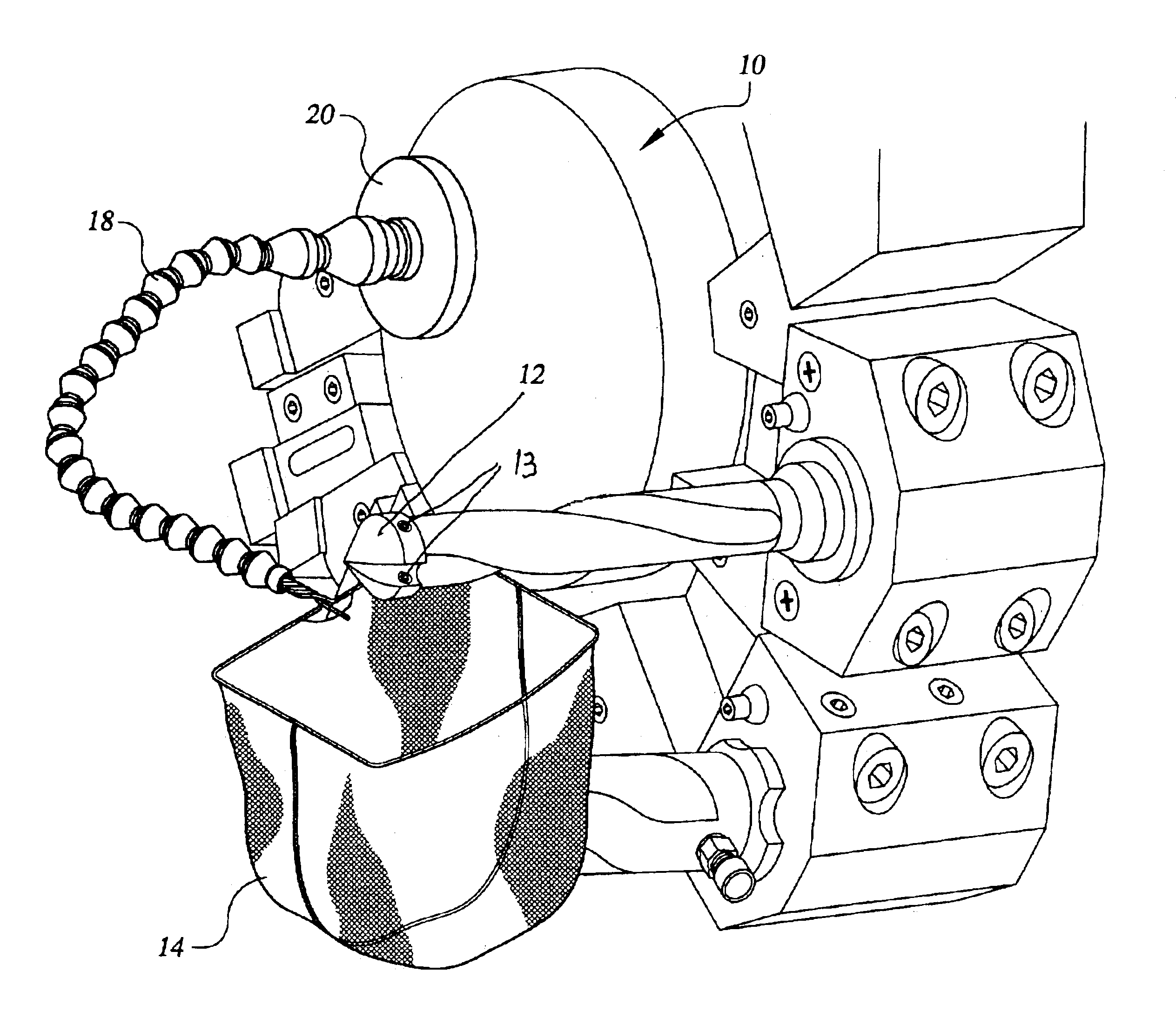
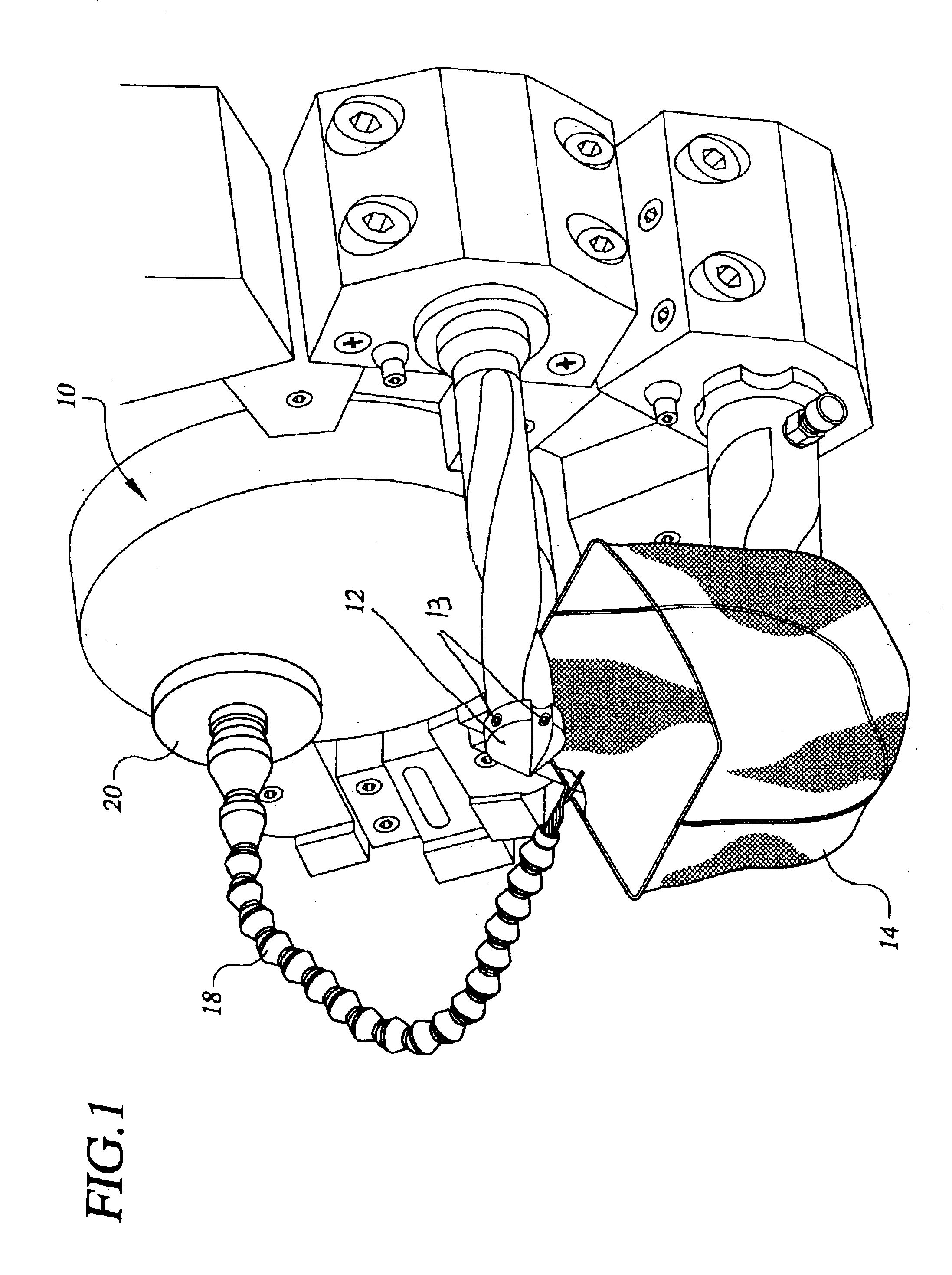
FIG. 1 is a perspective view showing a machine with a machine tool held by screws having a fastening means receiving and retaining device, in this case an open pouch, positioned beneath the machine tool and carried by one end of a cable, the other end of the cable being provided with a means for temporary attachment, in this embodiment, a magnet for magnetic attachment to the machine or machine adjacent surface.

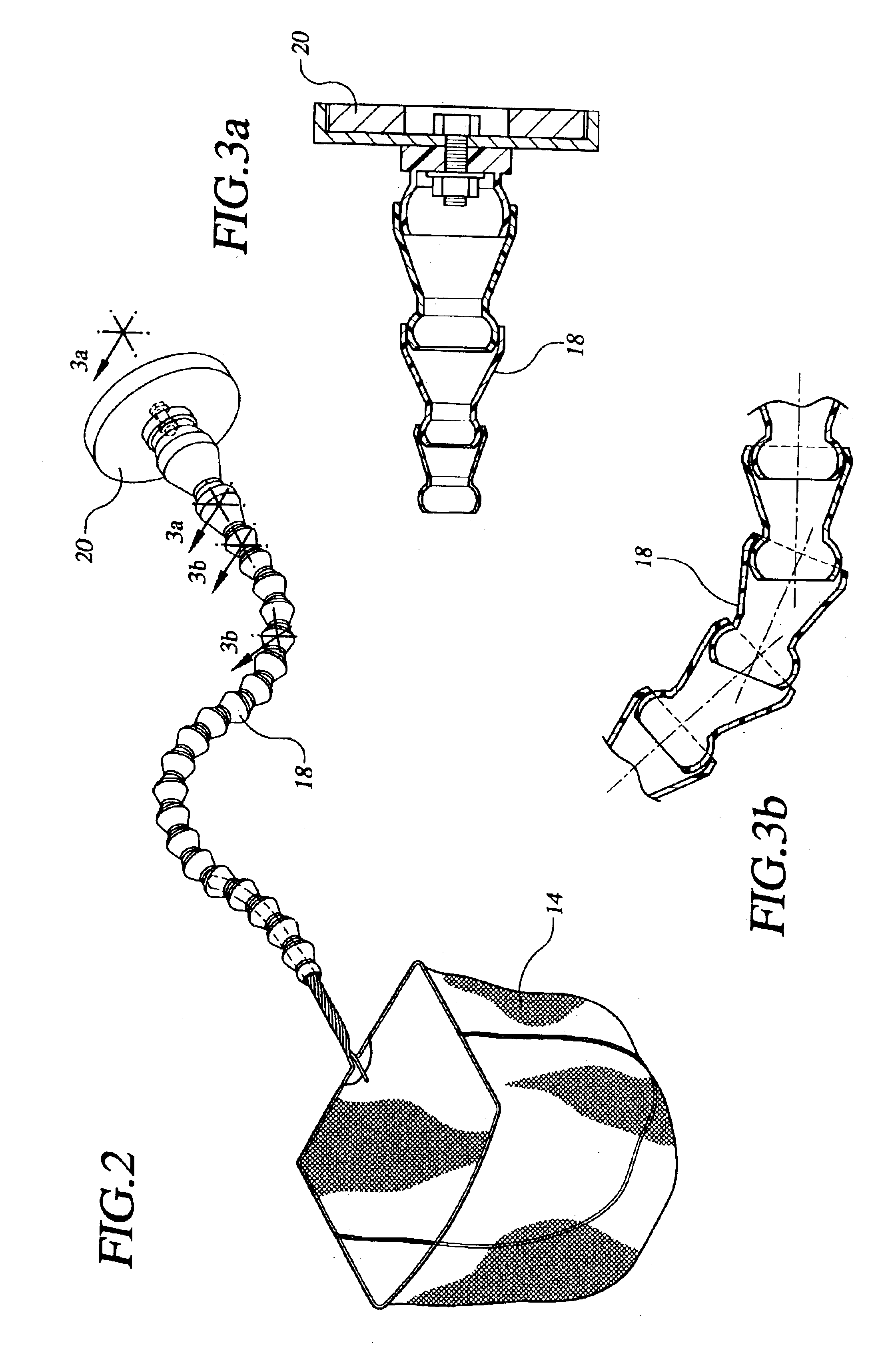
FIG. 2 is a perspective view of the pouch, cable and magnet.

FIG. 3a is a sectional view taken along the line 3a--3a in FIG. 2.

FIG. 3b is a sectional view taken along the line 3b--3b in FIG. 2.

FIG. 4 is a perspective view of an alternate embodiment of the invention wherein the means for temporary attachment is a C-clamp the free end of which is suitable for clamping to any projecting edge or surface of the machine (or support carrying or adjacent to the machine).

FIG. 5 is a perspective view of the same embodiment as is shown in FIG. 4 showing the C-clam...


PUM

PropertyMeasurementUnit
flexibleaaaaaaaaaa
structureaaaaaaaaaa
sizeaaaaaaaaaa

Abstract

A machine having a machine tool operatively connected thereto by manually manipulatable fastening members. A fastening member receiving and retaining device is adapted for placement beneath the machine tool for catching fastening members when inadvertently dropped. A device for temporary attachment to the machine or machine adjacent surface, and a flexible cable device are provided for connecting the fastening member receiving and retaining device to the for temporary attachment. The flexible cable device is adapted to be manually positioned and shaped and to retain its shape and position in a self-sustaining manner while holding the fastening member receiving and retaining device beneath the machine tool.

Description

BACKGROUND OF INVENTIONIn machine shops and the like, lathes and other metal working and materials forming equipment are equipped with tools for cutting, shaping and forming. These tools are subject to wear and tear over time and require fairly frequent changing for repair and reconditioning. The tools are also changed to suit the particular job at hand. The tools are joined or attached to the machine by fasteners such as screws.The tool changes are required to be performed frequently in many shops, particularly those having many machines.These fastening devices are usually fairly small and have acquired a coating of oil, grease and dirt making the required manual handling of the fastening devices an uncertain business. If a machine operator in attempting to manipulate the fastening devices in order to make a change of tool inadvertently drops the fastening device, he has to stop working at the task of tool changing in and attempt find the fastening device on the floor or perhaps re...

Claims


Application Information

Patent Timeline
Patent Type & Authority Patents(United States)
IPC IPC(8): B23Q13/00B23Q11/08
CPCB23Q11/08B23Q13/00Y10S29/079Y10S29/094Y10T82/30Y10T408/96Y10T409/30Y10T409/30392Y10T29/54Y10T83/97
Inventor SANCHEZ, JAVIER
Owner SANCHEZ JAVIER
Why Eureka
Try Eureka