High-density cable distribution frame

a high-density, fiber-optic cable technology, applied in the field of high-density fiber-optic cable distribution frames, can solve the problems of unsatisfactory or excessive fiber-optic cable displacement, bending and other forces, and prior art products that require substantial fiber-optic cable displacemen

Inactive Publication Date: 2003-11-11
ADC TELECOMMUNICATIONS +1
View PDF43 Cites 378 Cited by
  • Summary
  • Abstract
  • Description
  • Claims
  • Application Information

AI Technical Summary

Benefits of technology

According to a preferred embodiment of the present invention, a cable management system is provided which includes a fixture having a plurality of modules mounted on the fixture. Each of the modules is moveable on the fixture for movement along a line of travel. A releasable lock mechanism is provided for releasably locking each of the modu

Problems solved by technology

One problem associated with prior art high-density fiber distribution frames is that the prior art products require substantial displacement of fibers when access to the fiber connectors is required.
Unnecessary or excessive displacement of fiber optic cables is undesirable.
As fiber optic cables

Method used


Image

  • High-density cable distribution frame
  • High-density cable distribution frame
  • High-density cable distribution frame

Examples


Embodiment Construction

With reference now to the several drawing figures in which identical elements are numbered identically through-out, a description of the preferred embodiment of the invention will now be provided.

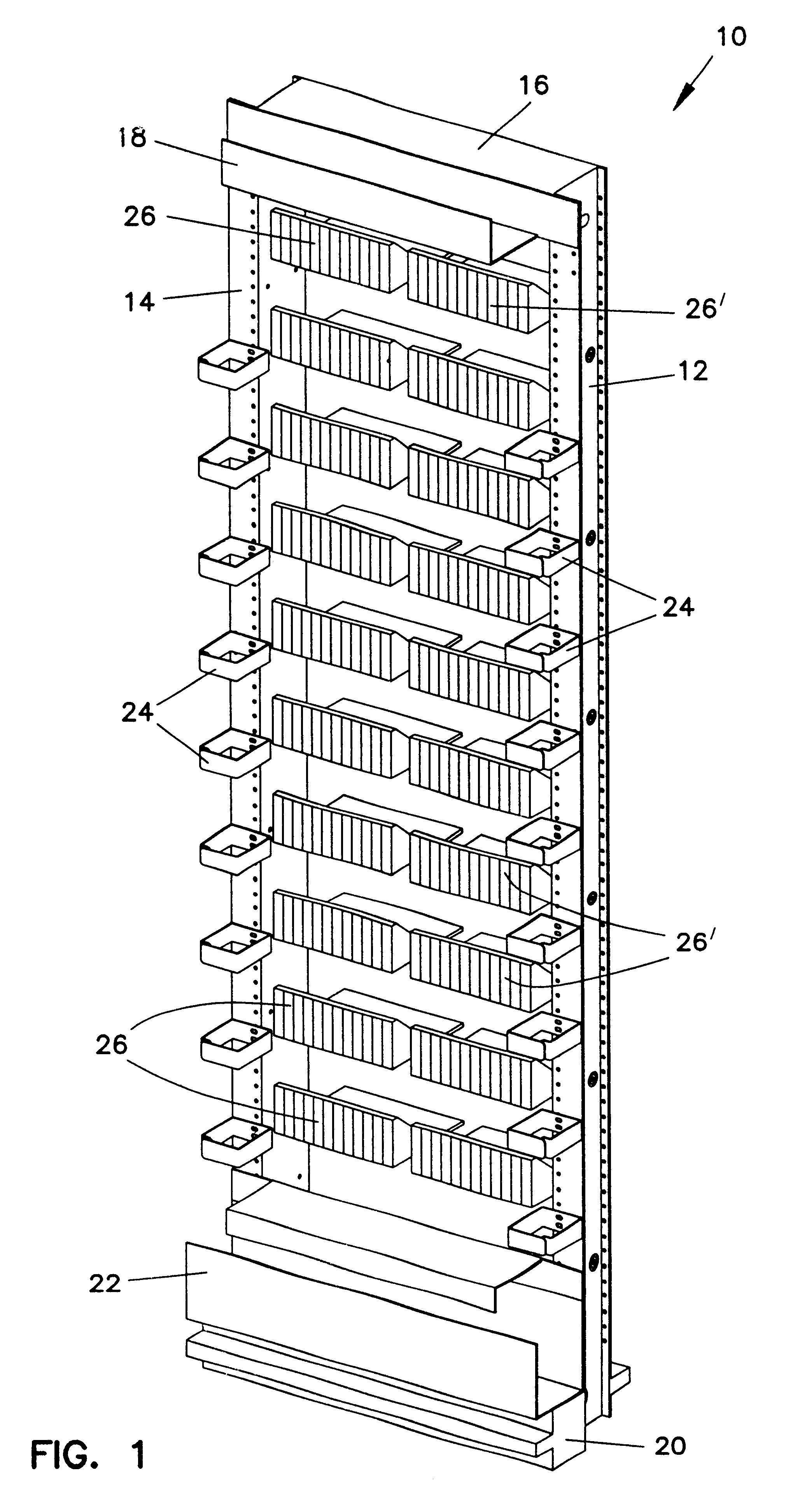
With initial reference to FIG. 1, a fiber distribution frame 10 is shown. The frame 10 includes spaced-apart side walls 12,14 connected at their upper ends by a top wall 16. Connected to the forward side of the top wall 16 is a trough 18 for carrying cables and the like as is conventional. The bottom of the frame 10 is provided with a pedestal 20 which also has secured to it a trough 22 for carrying cables and the like. The forward edges of the side walls 12,14 are provided with a plurality of clips 24 for holding fiber optic cables extending vertically in front of side walls 12,14.

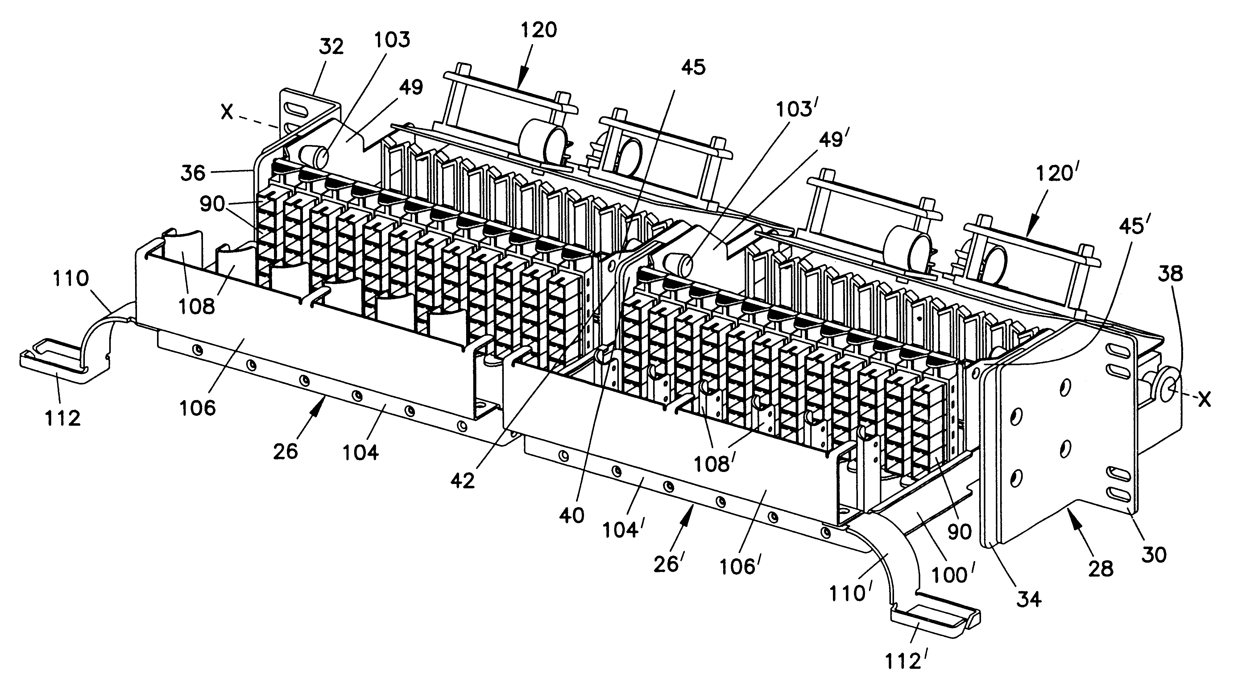
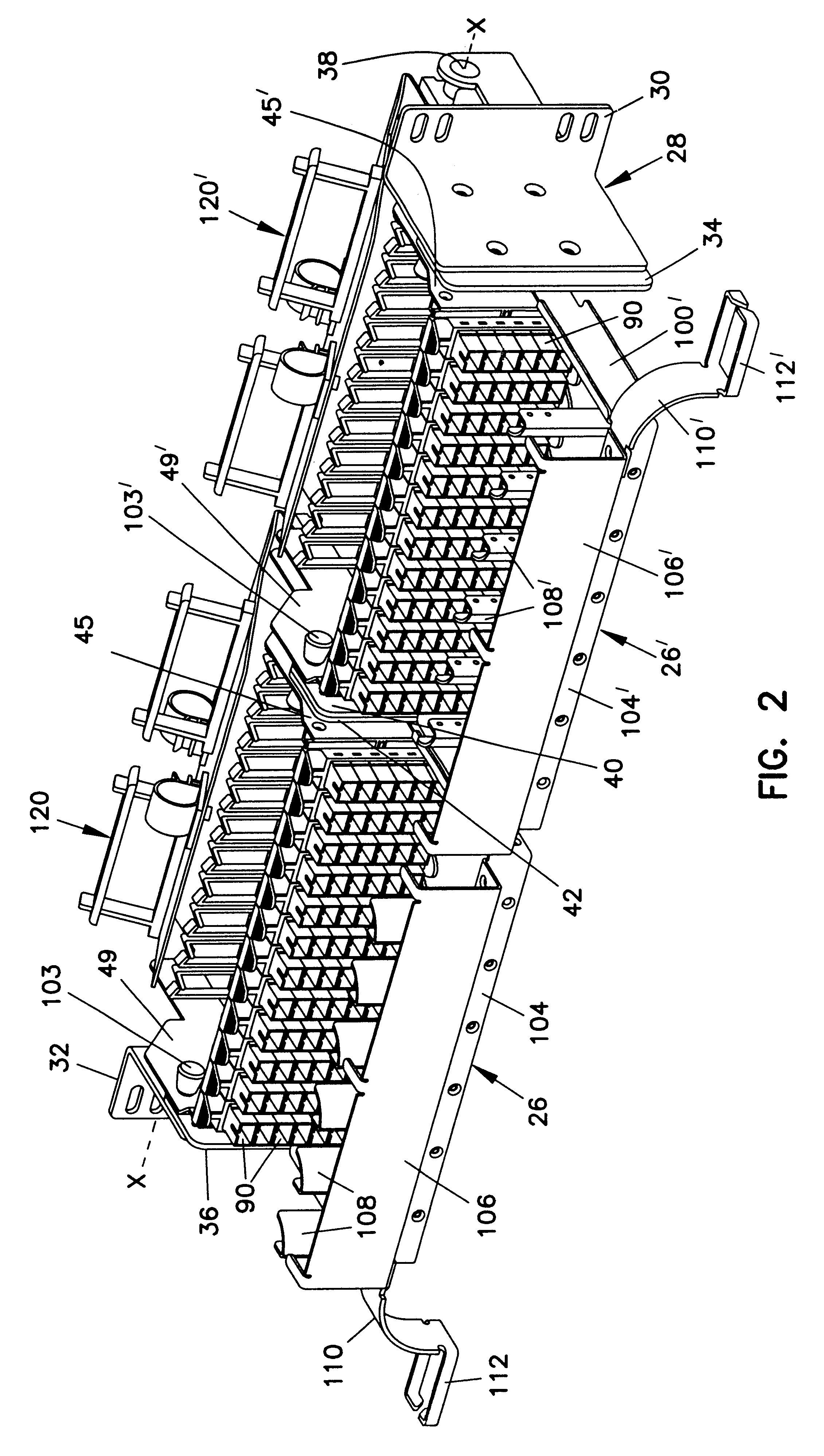
Contained within frame 10 between side walls 12,14 are a plurality of left and right mounting fixtures 26,26' (schematically shown in FIG. 1). A detailed description of mounting fixtures 26,26' is provided elsewh...


PUM


Abstract

A fiber distribution frame (10) includes a fixture (26) having a plurality of modules (58) mounted side-by-side within said fixture with each of the modules being individually mounted in a line of travel. Each of the modules (58) can be locked in any one of a plurality of discrete positions within the line of travel. Each of the modules (58) contains a plurality of adapters (90) for receiving and retaining fiber optic connectors. Further, the fixture (26) may be tilted downwardly to provide access to the rear of the fixture.

Description

BACKGROUND OF THE INVENTION1. Field of the InventionThis invention pertains to the telecommunications industry. More particularly, this invention pertains to a high-density fiber distribution frame for use in the telecommunications industry.2. Description of the Prior ArtIn the telecommunications industry, use of fiber optic cables for carrying transmission signals is rapidly growing. To interconnect fiber optic equipment, fiber distribution frames have been developed. An example of a prior art fiber distribution frame is shown in commonly assigned U.S. Pat. No. 4,995,688.To fiber distribution frame of U.S. Pat. No. 4,995,688 includes a so-called connector module (item 16 in the '688 patent) having a front panel which carries a plurality of adapters (102). Each of the adapters (102) permits attachment of a fiber optic connector (100) to both sides of the adapter in order to optically connect two fiber optic cables.Typically, the back side of the adapters (102) are provided with conn...

Claims


Application Information

Patent Timeline
IPC IPC(8): G02B6/00G02B6/44H04Q1/06H04Q1/02H04Q1/14G02B6/38
CPCG02B6/4452G02B6/4455H04Q1/06H04Q1/142H04Q1/066H04Q1/068H04Q1/021H04Q1/023H04Q1/062G02B6/3825G02B6/3897H04Q2201/804H04Q2201/02G02B6/44528G02B6/44524G02B6/44526
Inventor WHEELER, TODD A.
Owner ADC TELECOMMUNICATIONS
Why Eureka
Try Eureka