System and method for attaching drilling information to three-dimensional visualizations of earth models

a technology of earth model and three-dimensional visualization, applied in the field of system and method for attaching drilling information to three-dimensional visualization of earth model, can solve problems such as not utilizing these integrated applications, facing challenges to profitability

Inactive Publication Date: 2004-10-05
LANDMARK GRAPHICS
View PDF6 Cites 34 Cited by
  • Summary
  • Abstract
  • Description
  • Claims
  • Application Information

AI Technical Summary

Benefits of technology

For the purposes of this application, a definition of visualization may include the concept of binding (or mapping) of data to a representation that can be perceived. At a high level, the data being bound is that of an earth model and Drilling Information Management Systems (DIMS) operational data. An earth model may be defined as a spatial model of the earth surface and subsurface, containing a network of earth model objects, such as rock and fluid bodies. In one embodiment, an earth model may be generated in a project data environment, e.g. the integrated OpenWorks project data environment. Integration of the data from these different sources in the same visualizations may enable visual analysis. This system may prove particularly useful in representing this disparate data at once, in such a manner that the interdependencies can be made clear. The interactive data binding coupled with the 3-dimensional (3D) display will greatly enhance the ability to analyze these complex data sets and speed up the process of extracting information.
A benefit of this approach to visualizing data may be the speed of accessibility to the more valuable information captured on previous wells. This may allow drilling engineers and the other asset team members to better assess technical risk from the outset of prospect development and well planning, and to manage the risk more effectively.

Problems solved by technology

However, it faces challenges to profitability in years to come.
Drilling engineers tasked with wellbore construction typically do not utilize these integrated applications.

Method used


Image

  • System and method for attaching drilling information to three-dimensional visualizations of earth models
  • System and method for attaching drilling information to three-dimensional visualizations of earth models
  • System and method for attaching drilling information to three-dimensional visualizations of earth models

Examples


Embodiment Construction

The following documents are hereby incorporated by reference in their entirety as though fully and completely set forth herein:

Foley, J. and Ribarsky, B.: "Next Generation data visualization Tools", Georgia Institute of Technology, USA. (1994).

Dent, H.: "The Roaring 2000s", Simon & Schuster, New York (1998).

Yu, A.: "Creating the Digital Future", The Free Press, New York (1998).

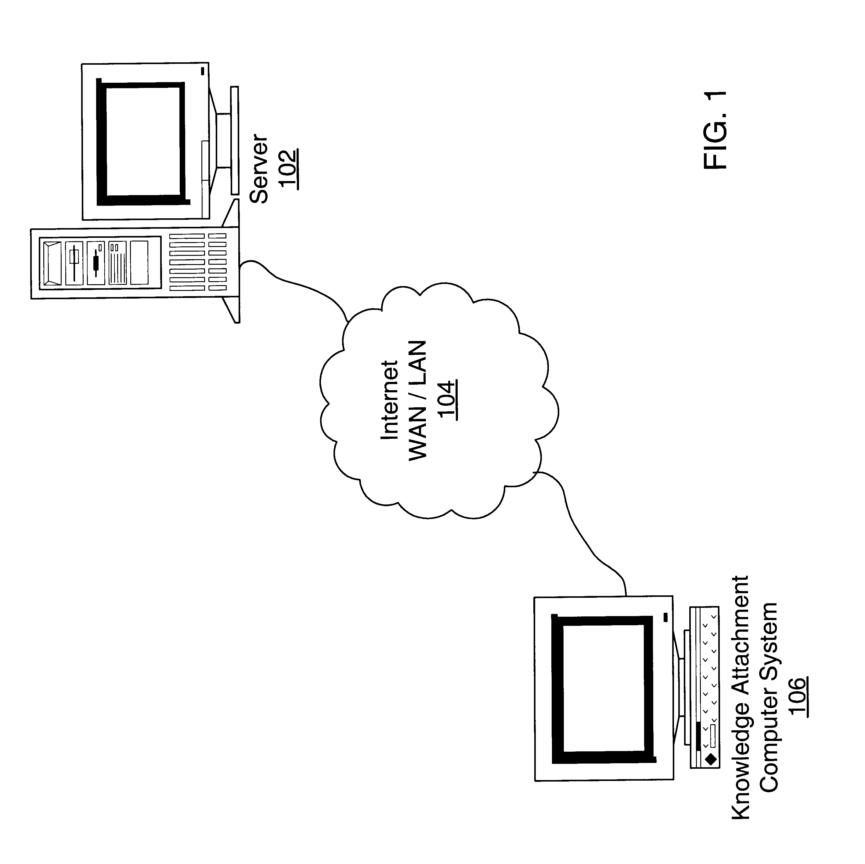
FIG. 1: Network System

FIG. 1 illustrates a simplified and exemplary network system according to one embodiment of the present invention. The embodiment illustrated in FIG. 1 includes one server 102 and one Knowledge Attachment computer system 106, which may be connected to a network 104 such as the Internet. However, it is noted that the present invention may be utilized with respect to any number of servers 102 and systems 106.

As shown, the server 102 may be connected to a network 104, in one embodiment the Internet 104. The Internet 104 is currently the primary mechanism for information interchange. However,...


PUM


Abstract

A system and method for perceiving drilling learning through visualization is provided. In one embodiment using three-dimensional visualization of the earth model as a foundation, a new IT development strategy focuses on perceiving "Drilling Learning" by an intuitive method. Symbols, known as "Knowledge Attachments" are attached to each wellbore trajectory displayed in the three-dimensional environment, with each symbol indicating a specific event-such as one related to drilling operations or problems. A Knowledge Attachment system proves particularly useful to represent disparate data at once, in such a manner that the interdependencies between the earth model and drilling operational data are evident and correlated. Operational issues and lessons learned from prior wells are easily accessed and perceived in the context of the earth model. By understanding this information at the beginning of the well planning process, operational efficiencies may be improved.

Description

The present invention generally relates to computer-based display of oil and gas exploration and production data. More particularly, the present invention relates to coupling drilling operational events and knowledge with an earth model in three-dimensional computer displays.DESCRIPTION OF THE RELATED ARTDuring the last 20 years, the Exploration and Production (E&P) business has been very successful in reducing the costs of finding and producing oil and gas reserves. However, it faces challenges to profitability in years to come. With the E&P industry competing for the same investment dollars as other industries, it is essential that operating companies continue to maximize the rate of return to their shareholders.E&P companies are now putting more focus on collaborative asset teamwork to better evaluate the economic viability and risk involved in developing prospective oil and gas fields. To facilitate such collaboration, E&P companies are adopting shared, integrated, IT technology...

Claims


Application Information

Patent Timeline
Patent Type & Authority Patents(United States)
IPC IPC(8): G01V1/28G01V1/34
CPCG01V1/34E21B44/00
Inventor SANSTROM, WILLIAM C.
Owner LANDMARK GRAPHICS
Why Eureka
Try Eureka