Sequential forming device

a technology of forming device and forming surface, which is applied in the field of devices, can solve the problems of striped tool marks on the surface of the plate member, uneven shape of the formed surface, and plate redundancy

Inactive Publication Date: 2004-11-30
HONDA MOTOR CO LTD
View PDF17 Cites 50 Cited by
  • Summary
  • Abstract
  • Description
  • Claims
  • Application Information

AI Technical Summary

Benefits of technology

Since the die-shaped pushing member is a concave die, the plate member is pushed and spread into the concave space of a lower die by the bar-shaped pushing member for forming. In this manner, it is possible to prevent the creases from being produced on the periphery of the forming section. Further, since the contacting section of the bar-shaped pushing member with the plate member is a flexible member, it is also possible to prevent the tool marks from being produced.
Since the flexible member is cylindrical and pivotably supported onto the tip section of the pushing member, the flexible member is adapted to contact the surface of the plate member rolling thereon. Accordingly, less friction results between the pushing member and the plate member thereby making the movement smooth.

Problems solved by technology

In this case, a shape of the formed surface is generally not uniform and thus the plate redundancy is caused.
Since the pushing member with high rigidity is pushed onto the plate member in a point contact condition, there is easily caused striped tool marks on the surface of the plate member.

Method used


Image

  • Sequential forming device
  • Sequential forming device
  • Sequential forming device

Examples


Embodiment Construction

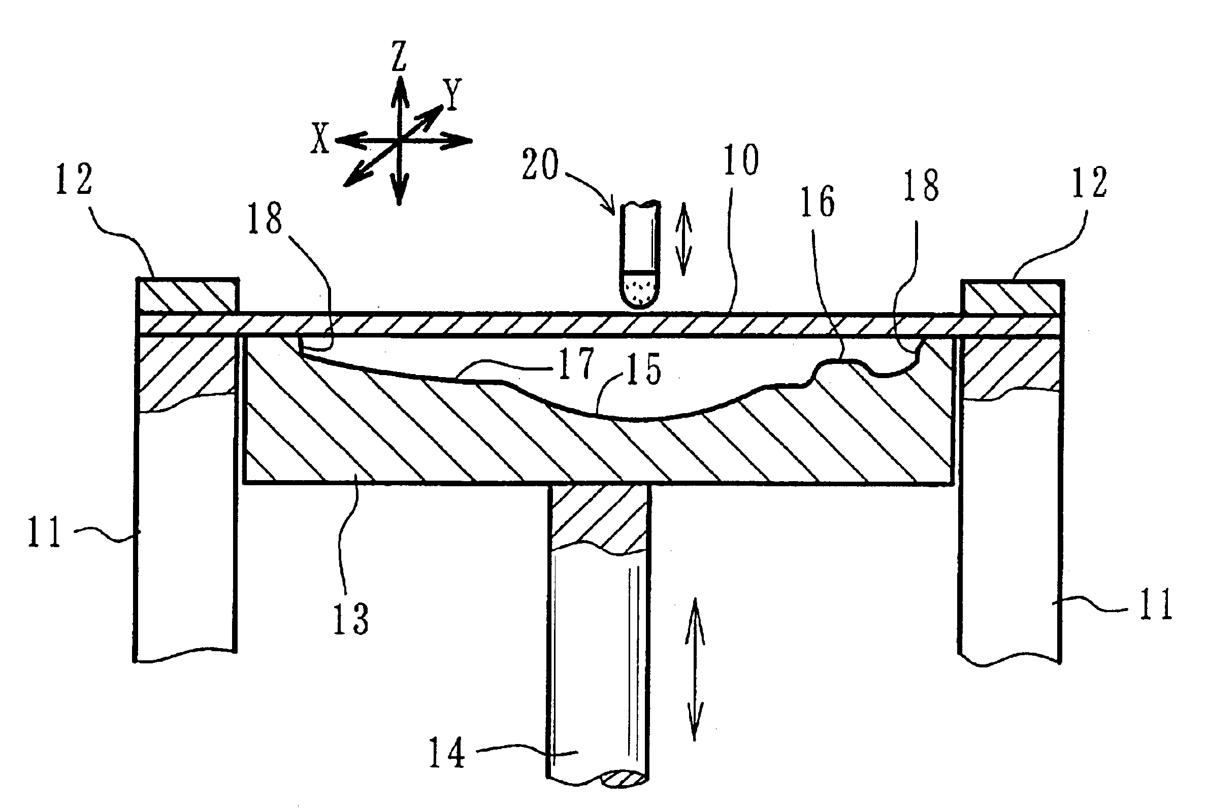
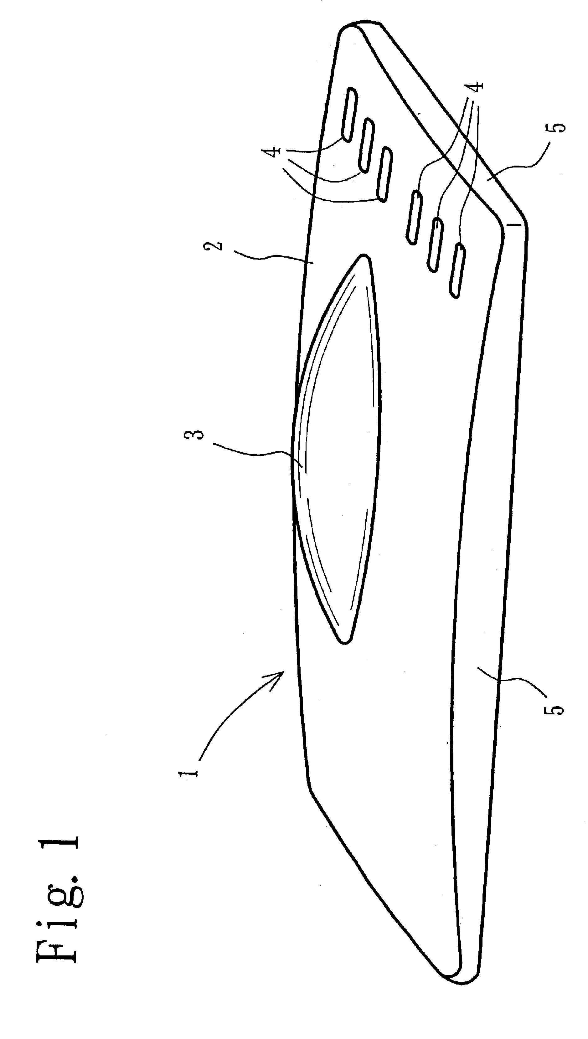
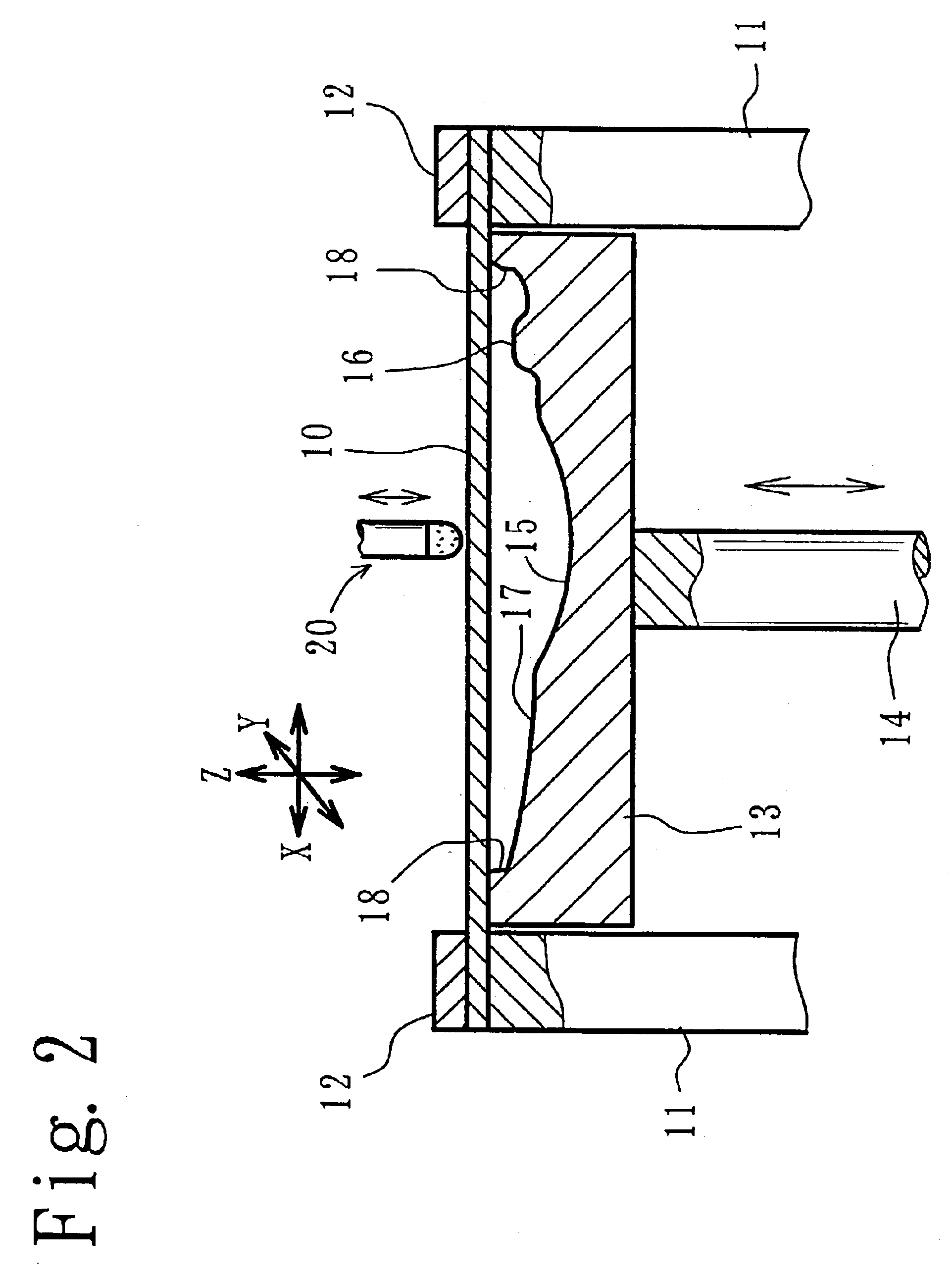
One embodiment of the present invention will be described with reference to the accompanying drawings. FIG. 1 shows an external appearance of a formed product obtained by the present sequential forming. FIG. 2 shows a principle of a sequential forming device and FIG. 3 is a partially enlarged cross-sectional view showing a principle of the sequential forming in a forming concave area. FIG. 4 is a view explaining a contour line described by a contacting section between a plate member and an upper pushing member. FIG. 5 is a partially enlarged cross-sectional view showing a principle of the sequential forming in a forming convex area. FIG. 6 is view showing a flexible member in a tip section of the pushing member. FIGS. 7 and 8 are views respectively showing the other embodiment of the flexible member.

Referring first to FIG. 1, a bonnet 1 is a sequential forming product of the present invention formed into a three-dimensional shape which becomes a surface shape of an automobile bonnet...


PUM

PropertyMeasurementUnit
stress concentrationaaaaaaaaaa
temperatureaaaaaaaaaa
flexibleaaaaaaaaaa

Abstract

A plate member (10) is mounted on a supporting frame (11). The periphery of the plate member (10) is firmly secured by a clamp (12) and a concave die-shaped lower pushing member (13) is caused to rise from below. The lower pushing member (13) is provided with a forming concave area (15) and a forming convex area (16). Disposed above the plate member (10) is a bar-shaped upper pushing member (20) which is lowered to push against the plate member (10). In such a condition, the plate member (10) is caused to rise together with the lower pushing member (13) and move in the directions of X and Y to form convex areas (17) and (18) within the forming concave area (15) and the forming convex area (16). The upper pushing member (20) is provided with a main body (21) of high rigidity and a flexible member (22). The flexible member (22) is formed in a hemispherical shape and made of material more elastic than the main body (21) which is made of hard polyurethane or the like, thereby making spherical contact with the plate member (10).

Description

BACKGROUND OF THE INVENTION1. Field of the InventionThe present invention relates to a device used in sequential forming. The sequential forming is a well-known method whereby a pushing member of a bar shape, a convex shape or a concave shape is provided to push on a metal member such as a metal sheet, wherein the metal member and the pushing member are caused to move relatively to have the plate member formed into a predetermined three dimensional shape such as a shell shape. In the present invention, two axial directions perpendicular to each other within a plane of the plate member before forming are referred to X and Y, while an axial direction perpendicular to each of them is referred to Z.2. Description of the Prior ArtThe sequential forming and the sequential forming device are disclosed in WO99 / 38627 and the like. For example, the sequential forming is disclosed in Japanese Unexamined Patent Publication No. Hei 5-42328 (1993). According to this sequential forming, four corne...

Claims


Application Information

Patent Timeline
Patent Type & Authority Patents(United States)
IPC IPC(8): B21D22/18B21D22/00B21D22/14B21D22/10
CPCB21D22/185B21D22/14
Inventor FUKUDA, KOUJIOZAWA, SHIGEO
Owner HONDA MOTOR CO LTD
Why Eureka
Try Eureka