
Position control for a crop pickup device

a pickup device and crop technology, applied in the field of agricultural harvesting machines, can solve the problems of not being able to maintain a uniform cutting height, automatic ground simulation is triggered too, damage to the finger bar as well as the ground,

Inactive Publication Date: 2004-12-07
CLAAS SELBSTFAHRENDE ERNTEMASCHINEN GMBH
View PDF25 Cites 101 Cited by
  • Summary
  • Abstract
  • Description
  • Claims
  • Application Information

AI Technical Summary

Benefits of technology

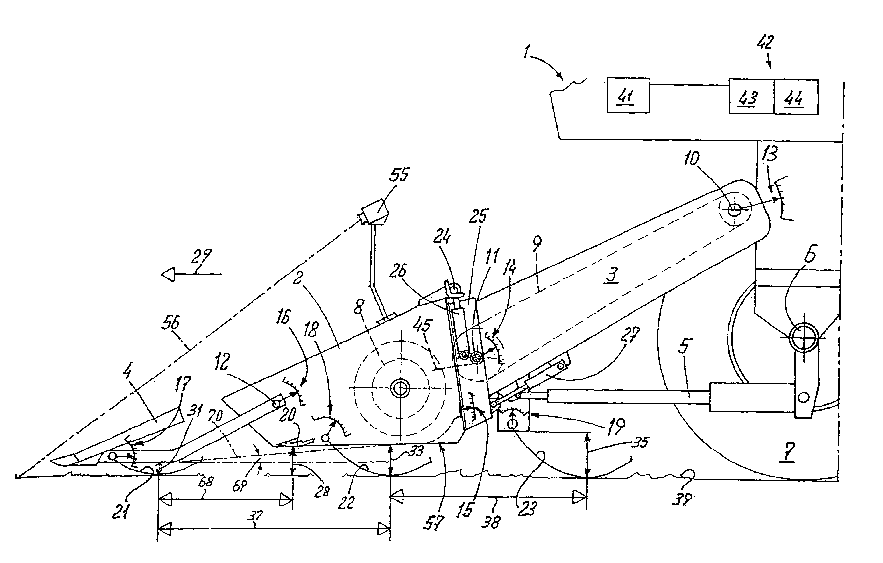
The present invention relates to a position control apparatus and method for a crop pickup device on an agricultural harvesting machine. The apparatus includes a measuring device for determining the distance from the crop pickup device to the ground at multiple points in the direction of travel, and a control device for automatically adjusting the position of the crop pickup device relative to the ground as a function of the measured distances. This allows for efficient pickup of the crop without damage to the crop pickup device or the ground, and provides a uniform cutting height for the finger bar. The invention also allows for instantaneous adjustment relative to the slope of the ground, and provides a more accurate measure of the inclination of the crop pickup device in relation to the slope of the ground.

Problems solved by technology

However, the ground sensors detect the ground profile only after picking up the crop, with the result that automatic ground simulation is triggered too late, and there can be damage to the finger bar as well as to the ground.
Further, it is not possible to maintain a uniform cutting height, particularly when the ground contour or profile has changed.
However, this kind of set up does not allow for instantaneous adjustment relative to the slope of the ground.
Therefore, particularly when the height of the ground has changed, the cutting angle cannot be optimally adjusted.
This may lead to early lowering of the header which can lead to placement of the header trough on the ground and hence damage the header.

Method used


Image

  • Position control for a crop pickup device
  • Position control for a crop pickup device
  • Position control for a crop pickup device

Examples


Embodiment Construction

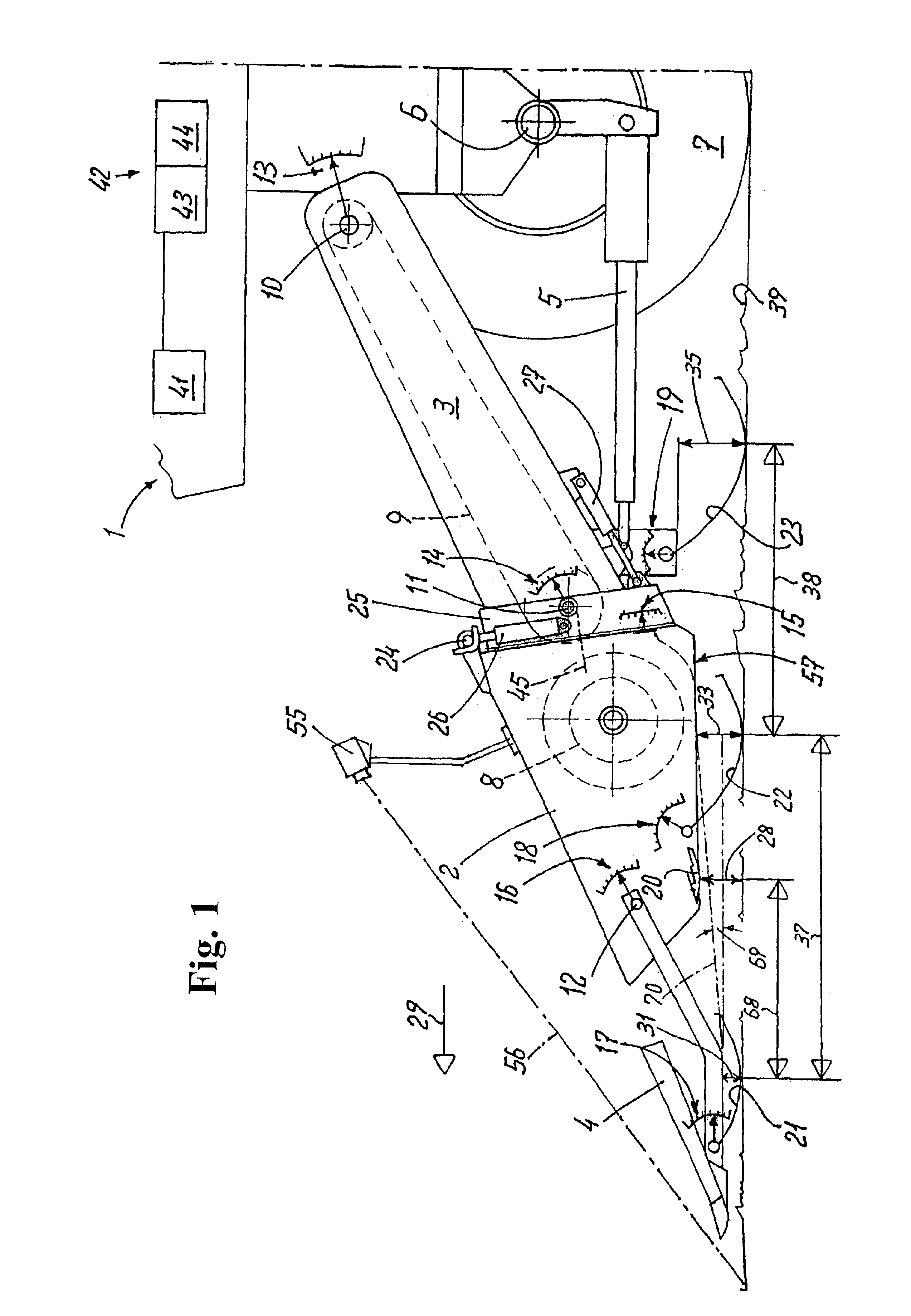
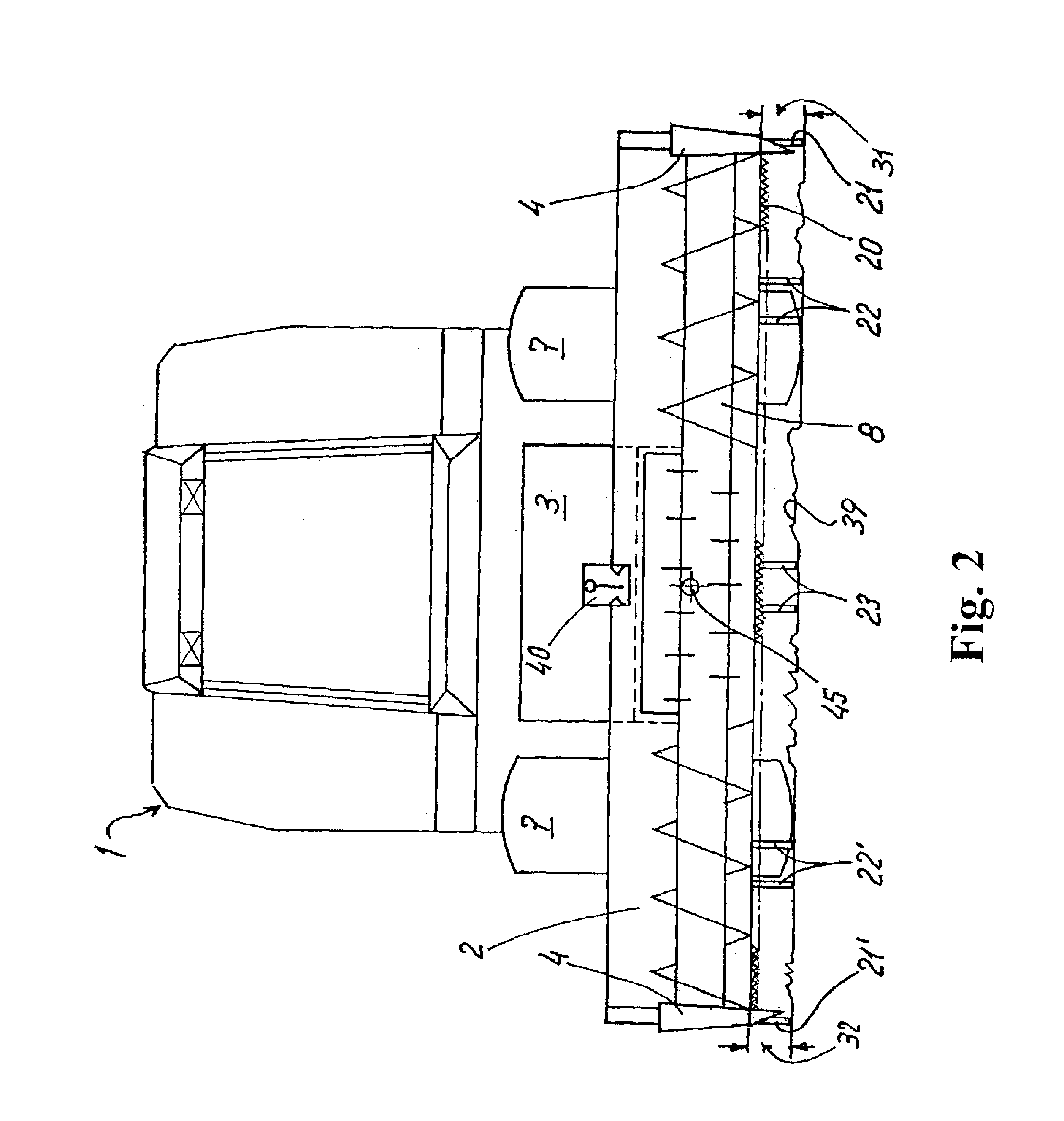
FIG. 1 shows a combine harvester 1 with a feeder housing 3 and a header 2 arranged at a front end thereof. The feeder housing 3 is arranged to be movable about a pivot axis 10 on the combine harvester 1 and can be pivoted by at least one lifting cylinder 5. The lifting cylinder 5 is linked to an axle 6 for vertical guiding of the header 2 over ground 39. A swinging adapter 25 is arranged at the front end of the feeder housing 3 in a direction of travel 29 of the combine harvester 1. The swinging adapter 25 is mounted movably on a transverse axis 11. At least one lifting cylinder 27 linked to the feeder housing 3 engages the swinging adapter 25 with its piston rod and enables controlled pivoting of the swinging adapter 25 about the transverse axis 11. The header 2 is mounted so as to be pivotable about an ideal longitudinal axis 45 (best seen in FIG. 2). For this purpose, lifting cylinders 26 are arranged on each of the two sidewalls of the swinging adapter 25. The respective piston ...


PUM


Abstract

A position control for a crop pickup device which is mounted for vertical movement relative to an agricultural harvester. A measuring device is provided for determining the distance from the crop pickup device to the ground, wherein the position of the crop pickup device relative to the ground is adjustable by one control device as a function of the measured ground distance. The distance to the ground is determined by the measuring device at two points spaced from each other in the direction of travel. As a result, advantageously the inclination of the ground can be determined and used for optimized control of ground simulation of the crop pickup device. Additionally, the cutting angle can be adapted automatically to the slope of the ground, to avoid crop losses and impede damage to the grain header.

Description

This application claims foreign priority under 35 USC .sctn.119 to prior foreign application 102 27 484.3 filed in Germany on Jun. 19, 2002.The invention relates generally to agricultural harvesting machines and, more specifically, to an apparatus and a method for position control of a crop pickup device.DESCRIPTION OF THE RELATED ARTAgricultural harvesting machines generally pick up crop by a crop pickup device. The crop pickup device has the function of picking up the crop to the ground without crop losses and without damage to the crop pickup device or to the ground.Crop pickup devices are commonly referred to as headers, such as grain headers, forage headers, and corn headers. Crop pick devices generally cut the crop from the field before picking up the crop. Some crop devices, such as corn pickers and grain strippers, separate the cobs or the ears from the crop and then pick them up. Other crop devices pick up the crop previously cut from the field and gather the cut crop into ...

Claims


Application Information

Patent Timeline
Patent Type & Authority Patents(United States)
IPC IPC(8): A01D41/00A01D41/14
CPCA01D41/141
Inventor THIEMANN, HOLGERUHLENDING, HUBERTDAMMANN, LUDWIG
Owner CLAAS SELBSTFAHRENDE ERNTEMASCHINEN GMBH
Learn More