Heat pipe for differential assembly

a technology of differential assembly and heat pipe, which is applied in the direction of indirect heat exchangers, machines/engines, lighting and heating apparatus, etc., can solve the problems of axle lubricant durability and the axle itsel

Inactive Publication Date: 2004-12-14
TORQUE TRACTION TECH INC
View PDF21 Cites 41 Cited by
  • Summary
  • Abstract
  • Description
  • Claims
  • Application Information

AI Technical Summary

Problems solved by technology

Operating temperatures significantly above 250 degrees F can begin to cause problem

Method used


Image

  • Heat pipe for differential assembly
  • Heat pipe for differential assembly
  • Heat pipe for differential assembly

Examples


Embodiment Construction

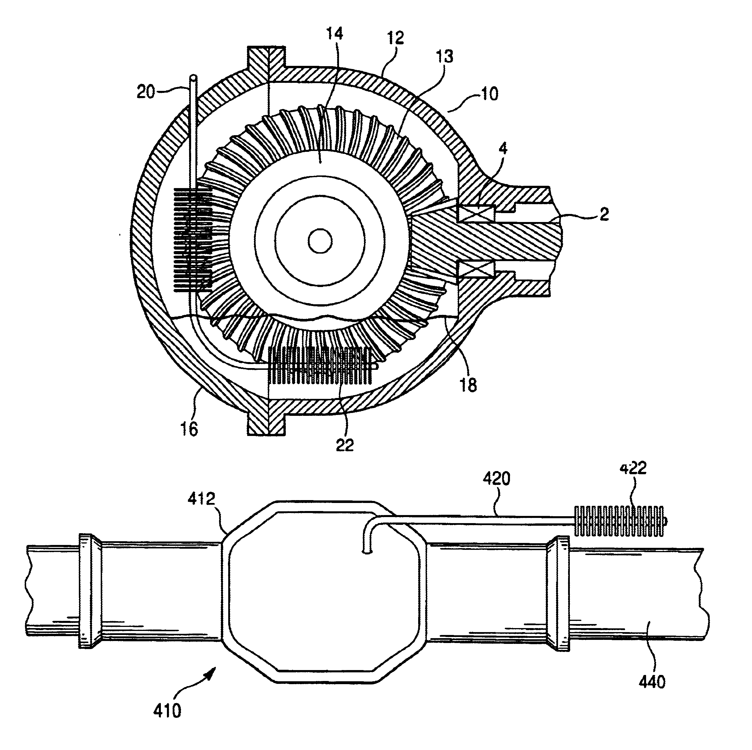
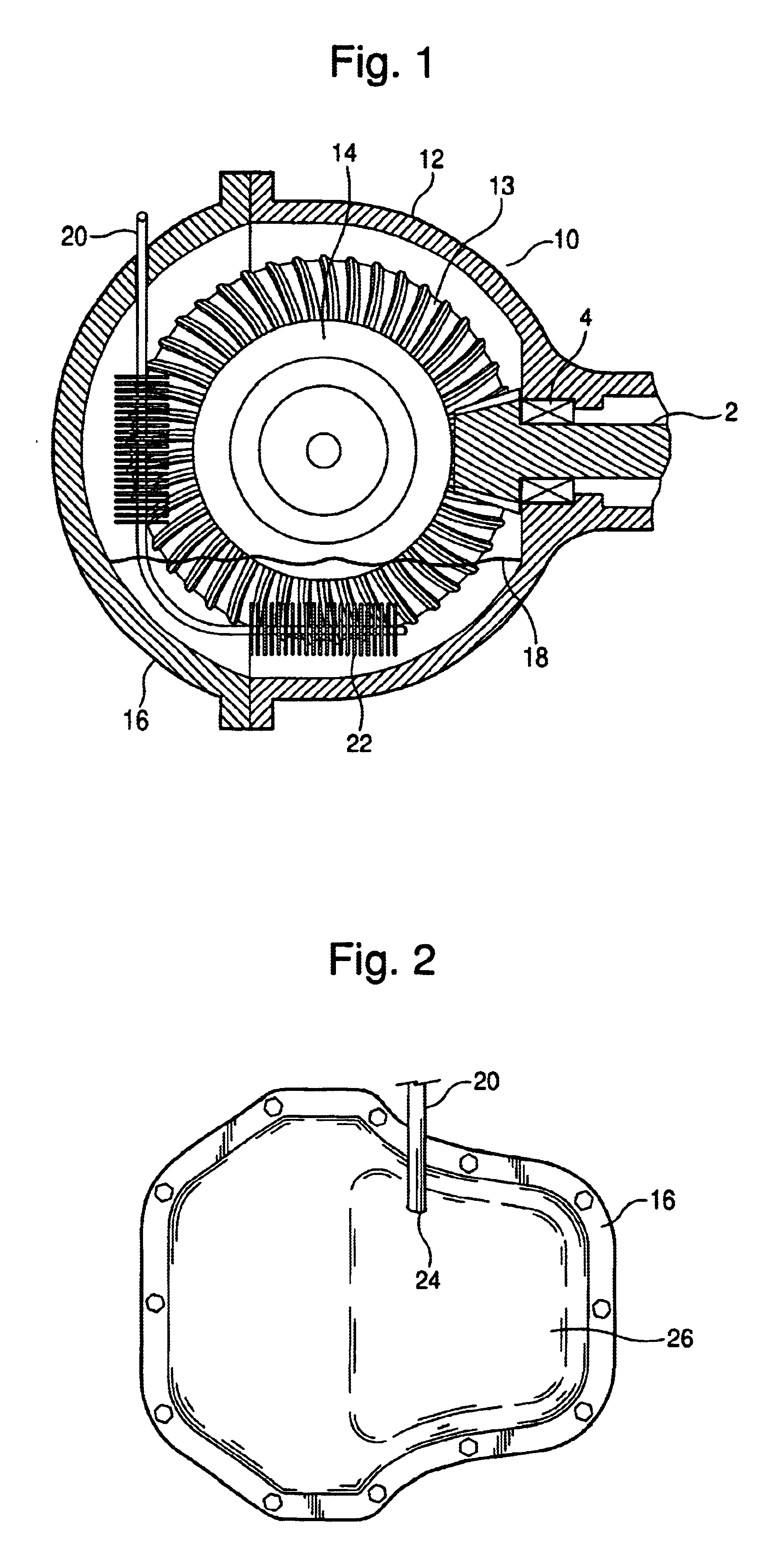
The features of the invention as explained above provide a temperature regulating apparatus (i.e., cooling means) for an axle assembly 10.

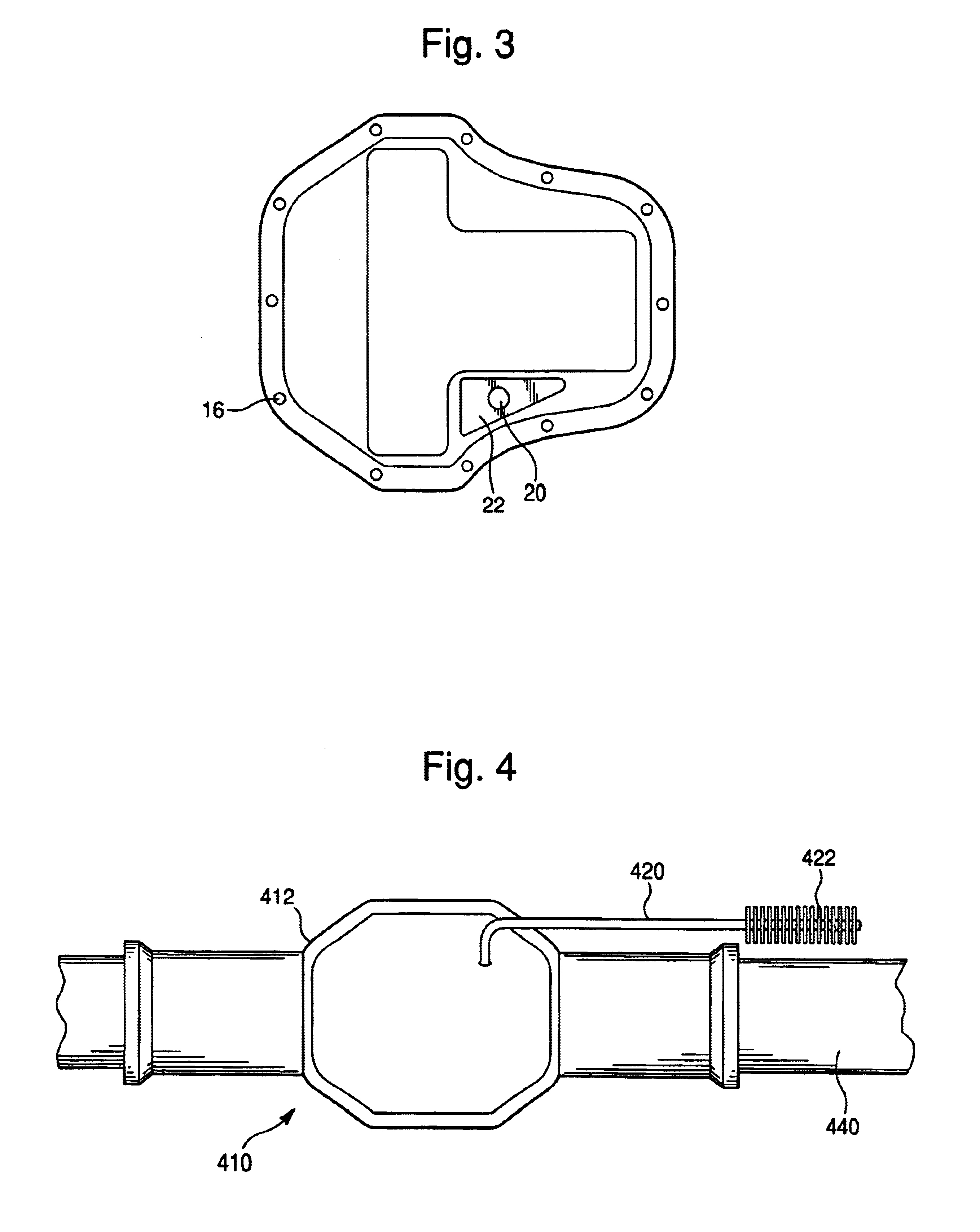
Referring to FIG. 1, a differential assembly 14 is disposed with in an axle carrier 12. The axle carrier 12 is open in the rear and has a corresponding cover 16 for sealing the assembly 10. The carrier 12 houses a pinion shaft 2 that defines an axial direction. The pinion shaft 2 drivingly engages a ring gear 13 of the differential assembly.

Vehicle torque transmitting devices, such as axle assemblies, require lubricating fluid 18 in order to allow the moving gears within the assemblies to properly function. Temperature of lubricating fluid 18 within the axle assembly 10 varies depending upon several conditions, including but not limited to ambient temperature, speed, torque, etc. During initial driving conditions of the vehicle and operation under high speeds, the axle assembly 20 is relatively hot which results in inefficient operation. The lubri...


PUM


Abstract

An apparatus to regulate and control the temperature of an axle assembly for a vehicle. A heat pipe is inserted though the axle housing cover, the heat pipe travels the length of the cover. Near the lower region of the carrier and beneath the lubricating fluid level, the heat pipe bends to continue in the horizontal direction. Disposed about the terminal end of the heat pipe below the lubricating fluid line are a series of cooling fins. Heat generated within the lubricating fluid that is heated during operation conduit is dissipated via the cooling fins.

Description

1. Field of the InventionThe present invention relates to a differential assembly that is lubricated to prevent excessive heat buildup. More specifically the present invention relates to an apparatus that removes heat from the axle assembly or torque transmission device.2. Description of Related ArtTypically axles are lubricated by a reservoir of oil in the sump which is circulated by the moving components. This is known as splash lubrication. The operating temperature of a splash lubricated axle assembly or other torque transmission device is generally dependent on the torque being transmitted, the ambient temperature, the speed of rotation and airflow over the device.The operating temperature can be just above the ambient temperature to more than 200 degrees F above ambient. Operating temperatures significantly above 250 degrees F can begin to cause problems with the durability of the components in the axle as well as the lubricant itself. These temperatures are generally encounte...

Claims


Application Information

Patent Timeline
IPC IPC(8): F16H57/04F28D15/02F01P3/22F16N39/00F16N39/02
CPCF16H57/0412F16H57/0415F16H57/0483F28D15/02F01P2003/2278Y10T74/19991Y10S165/916Y10T74/2189F16N39/02
Inventor FETT, GREGORY ALLENRUNSTADLER, TIMOTHY WILLIAMKRUEGER, DAVID ALLENDOUGHERTY, MICHAEL L.
Owner TORQUE TRACTION TECH INC
Why Eureka
Try Eureka