Gate

a technology for gates and doors, applied in the field of gates, can solve the problems of restricting the size of the building in which the gate assembly is installed, affecting the operation of the gate, and being particularly hazardous to the operator, so as to achieve less maintenance, less room in the open position, and less complicated

Inactive Publication Date: 2004-12-28
PICKIN CHRISTOPHER DOUGLAS +2
View PDF10 Cites 6 Cited by
  • Summary
  • Abstract
  • Description
  • Claims
  • Application Information

AI Technical Summary

Benefits of technology

This has the advantage that the operator has more room to pass the open gate assembly, this is of particular importance when there is a gate assembly either side of the pit.
This has the advantage that it provides more clearance from the ground when the barrier is being opened and closed. This also means that the barrier can be mounted in a lower position relative to the ground than would otherwise be possible.
The present invention overcomes this problem as there is now adequate clearance for all the animals to progress through the passageway without having to negotiate around any part of the barrier.
It can be seen that the present invention has other advantages over the prior art, the most significant being that the barriers open wider and higher than any of the previous gating systems, and also take up less room in the open position than with the standard pitswing gate.
Another advantage of the present invention is that the one piece linking system between the two barriers is less complicated and more durable than those used with other pitswing gating systems and therefore also requires less maintenance.
A further advantage is that due to the inclusion of a box-section assembly, rather than normal tubular assembly, the pivot mounting assembly is also far more durable.

Problems solved by technology

However, whilst fairly effective, this design does have a number of drawbacks.
When the milking parlour is in operation the environment is generally damp and therefore corrosion is an ever present problem.
Corrosion of the counter balance weight assembly is of particular concern as if the weight was to be come detached from the gate assembly it could be particularly hazardous for the operator.
Another significant problem with a single pivoting gate is that it must be of a considerable size in order to block the passage of animals and there must therefore be a large movement of the gate in order to clear the passage when the gate is opened.
This therefore restricts the size of the building in which the gate assembly can be used.
A further problem with this style of gate is that the pivot point, about which the gate rotates, is generally clamped around a top bar of the mounting frame.
This is generally accepted to be a weak point of the system as when the gate is leant on or banged against by an animal this bracket can either rotate or be damaged thereby rendering the gate either difficult to operate or ineffective.
Whilst improving some of the problems found with the foregoing systems, the pitswing gate system introduced a new problem in that the animals would often attempt to force their way through the gap between the two gates, or sometimes would attempt to climb over the gates.
A further problem found with the pendulum gate system is that quite often animals that were close to the gate when they opened would need to back up in order to clear the gate and continue along the passageway.
Whilst the pitswing gate assembly reduced the amount of clearance needed in order for the gates to operate, the gate which moves away from the pit still requires a considerable area in which to operate properly.
A further problem introduced by the pitswing gate assembly is that the control and linking mechanism for the two gates is constructed of several elements and is quite complicated in its operation.

Method used


Image

  • Gate
  • Gate
  • Gate

Examples


Embodiment Construction

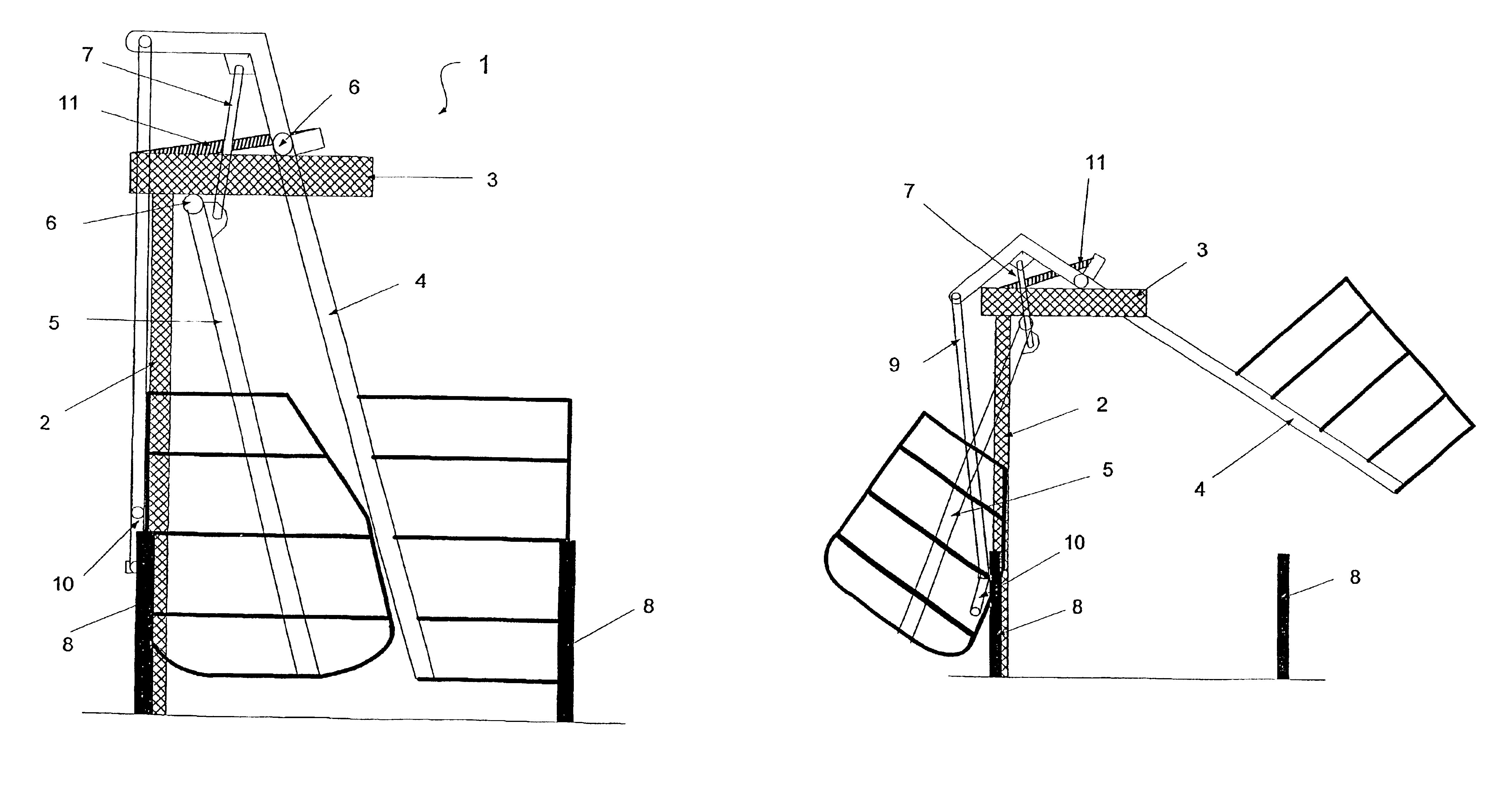
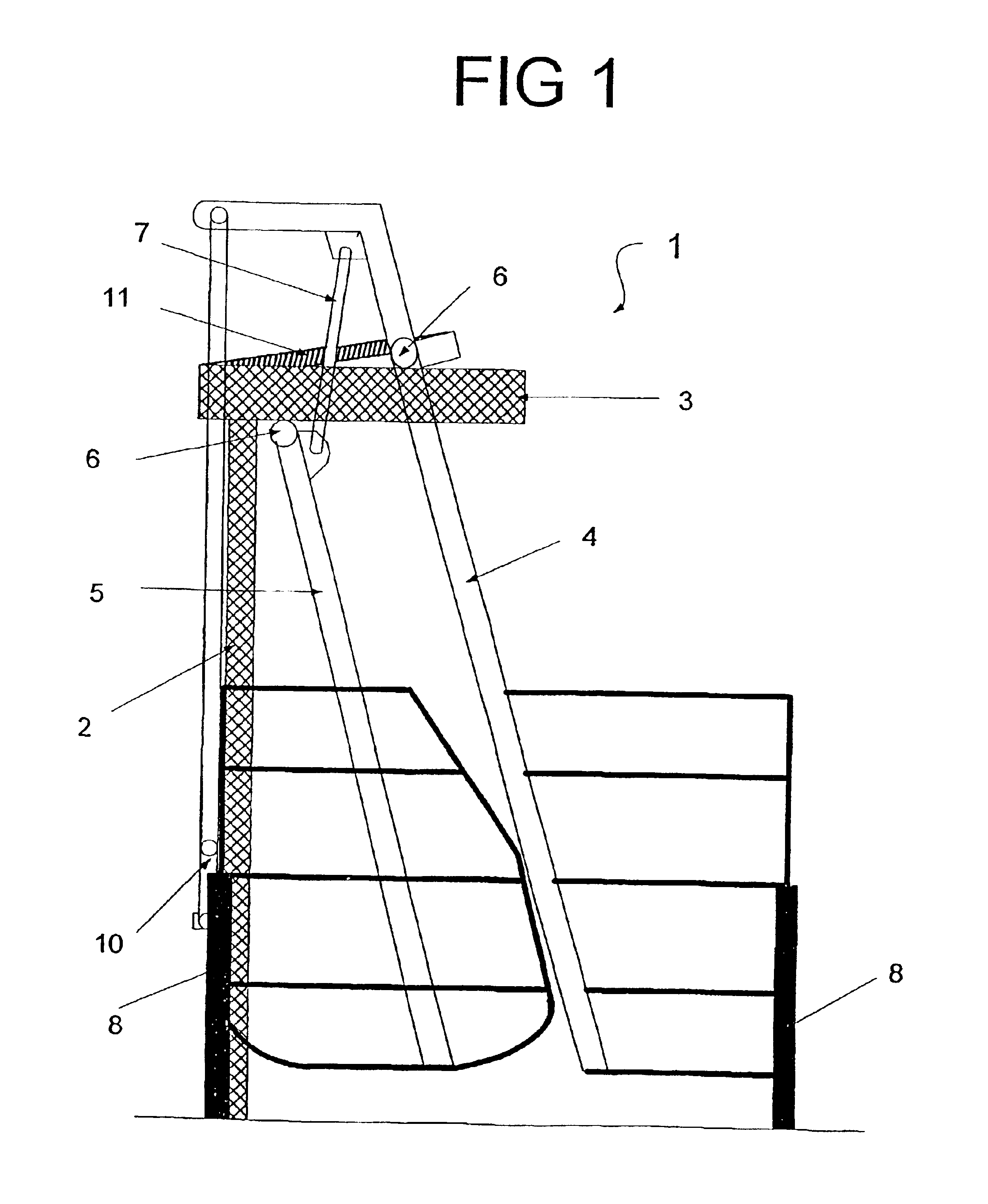
With respect to the figures, there is illustrated a preferred embodiment of the present invention generally indicated by arrow 1.

The gate assembly 1 includes a support stanchion 2 to which the box section cage 3 is mounted.

The outer gate 4 and inner gate 5 are mounted to the box section cage 3 via pivot 6.

The gates 4, 5, are joined via an adjustable linking rod 7.

The gate assembly 1 can be fitted with a set of restraining struts 8 in order to ensure an animal cannot force the gates 4, 5, forward and thereby damage the gate assembly 1.

The operator controlled gate activation lever 10 is connected to the gates 4, 5, via an adjustable linking rod 9.

The weight of the gates is counterbalanced by a spring 11, which is mounted between the box-section cage 3 and the outer gate 4.

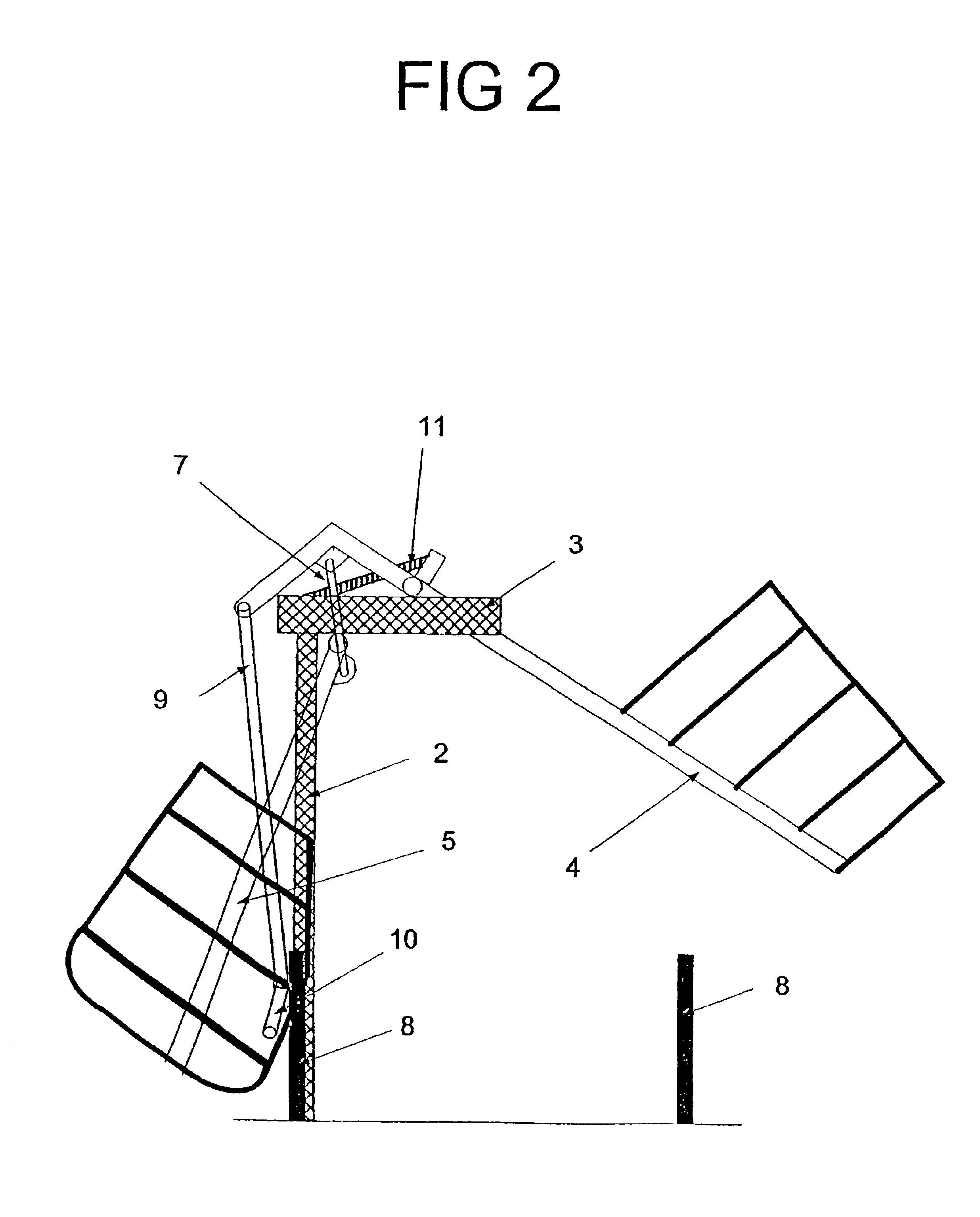
FIG. 2 shows the gate assembly 1 in the open position, highlighting how the inner gate 5 withdraws from the passageway so that its inner edge is level with the support stanchion 2.

The outer gate 4 is raised high enou...


PUM


Abstract

A gate assembly for an animal passageway has two barriers that, when in use, are in close proximity to each other in a closed position and can be moved in opposing directions to each other to be in an open position. The operation of the gate assembly to the open position is achieved by an operator using an operator-activated control mechanism. At least one barrier is configured so that when in the open position it does not intrude into the passageway and activation of the control mechanism is external to the passageway. The gate assembly is maintained in the open position until the operator operates the control mechanism to close the grate assembly. When the assembly is in the open position one barrier is in an upper position with respect to the other. The barrier are pivotally attached to a support at separate pivot points.

Description

This invention relates to a gate. In particular, this invention relates to the gating system for use in animal husbandry. Reference throughout this specification should now been made to use of the present invention for controlling the passage of animals, and in particular cows, within a milking shed.However, this should not necessarily be seen to be a limitation on the present invention.Gating systems for controlling the flow of cattle within milking sheds are well known within the Dairy Industry.Historically, one of the better designs available was a single, counter-balanced gate, with a single pivot point located towards the top of the gate, and rotated around a horizontal axis.A contemporary example of a single counterbalanced gate would be U.S. Pat. No. 4,567,851. However, whilst fairly effective, this design does have a number of drawbacks.The opening of the gate was controlled by an operating lever which was used to swing the gate upwards around its pivot point.A counter-balan...

Claims


Application Information

Patent Timeline
Patent Type & Authority Patents(United States)
IPC IPC(8): A01K1/00
CPCA01K1/0017
Inventor PICKIN, CHRISTOPHER DOUGLASHARRIS, JAMES ARTHURVAN AMSTERDAM, JOHN PETER
Owner PICKIN CHRISTOPHER DOUGLAS
Why Eureka
Try Eureka