Control system for, and a method of, disengaging a hydraulically-driven implement from a work machine

a control system and hydraulically-driven technology, applied in the field of work machines, can solve the problems of not being able many methods have not been applied to aid in the disengaging of an interchangeable hydraulically-driven implement from a work machine, and it is difficult to disconnect the hydraulic lines from the attachment ports via quick disconnectors

Inactive Publication Date: 2005-01-04
CATEPILLAR SARL
View PDF33 Cites 16 Cited by
  • Summary
  • Abstract
  • Description
  • Claims
  • Application Information

AI Technical Summary

Benefits of technology

In one aspect of the present invention, a work machine includes a hydraulically-driven implement operably coupled to a work machine body via at least one hydraulic line. At least one valve is operably coupled to an electrical actuator and is moveable between, at least, a first and a second position. A pressure release controller is operably coupled to energize t

Problems solved by technology

Engineers have long known that opening a closed hydraulic system, such as a hydraulic system connecting the hydraulically-driven implement to the work machine body, can be difficult, and often undesirable, when high pressure is trapped within the system.
Although these pressure relieving methods have found use in various situations, many of the methods have not been applied to aid in the disengaging of an interchangeable hydraulically-driven implement from a work machine, such as a skid steer loader.
Thus, when the operator attempts to detach the implement from the skid steer loader, the trapped high pressure fluid can make it difficult to disconnect the hydraulic lin

Method used


Image

  • Control system for, and a method of, disengaging a hydraulically-driven implement from a work machine
  • Control system for, and a method of, disengaging a hydraulically-driven implement from a work machine
  • Control system for, and a method of, disengaging a hydraulically-driven implement from a work machine

Examples


Embodiment Construction

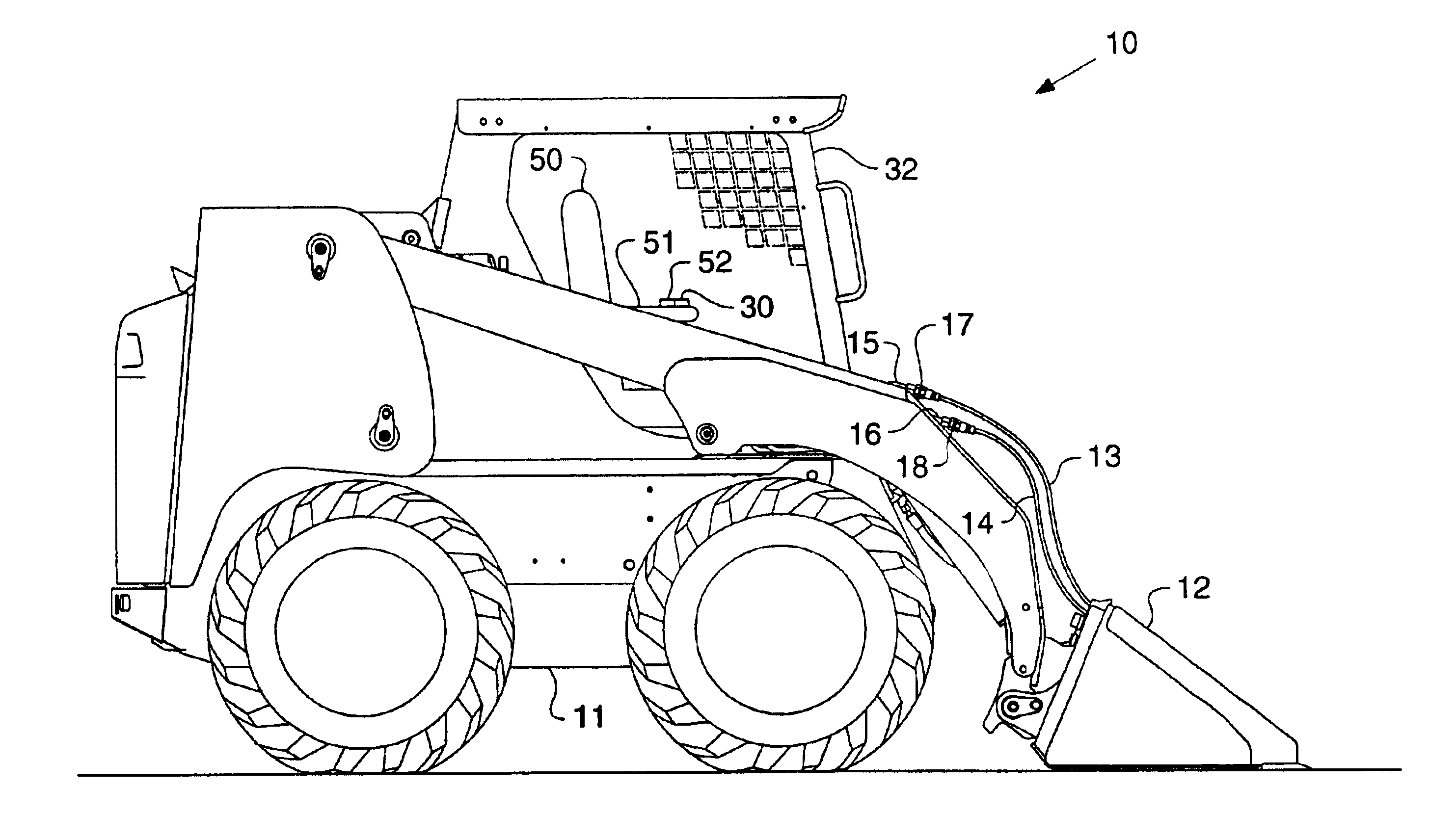
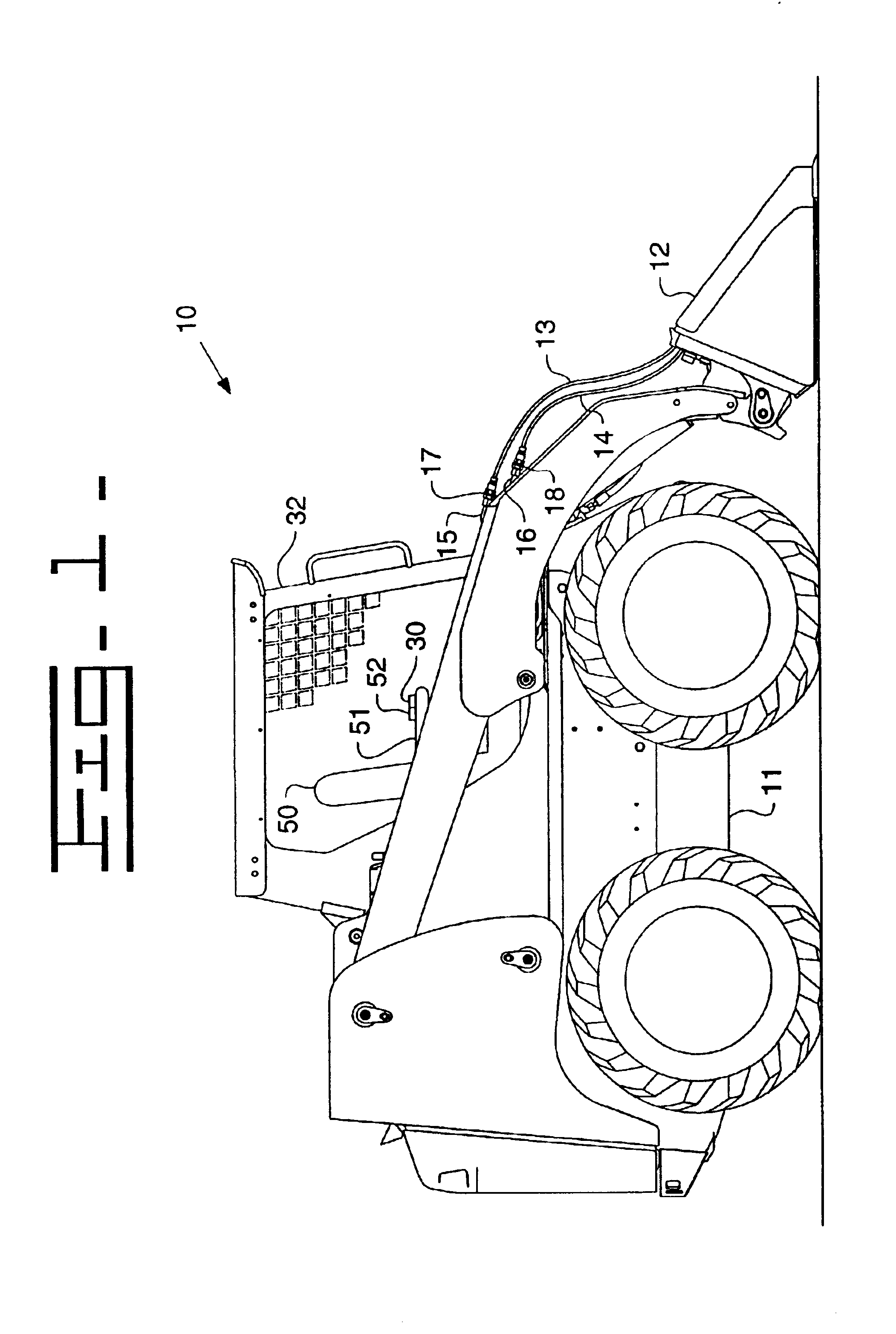
Referring to FIG. 1, there is shown a side view of a work machine according to the present invention. Although the work machine 10 is preferably a skid steer loader, it should be appreciated that the work machine10 could be any type of work machine 10 to and from which interchangeable hydraulically-driven implements can be attached and detached. Further, although the interchangeable hydraulically-driven implement is illustrated as a broom 12, it should be appreciated that various interchangeable hydraulically-driven implements, including but not limited to augers, cold planers, buckets and trenchers, could be attached to the work machine body 11. The broom 12 is operably coupled to a work machine body 11 via a first hydraulic line 13 and a second hydraulic line 14. Although the present invention is illustrated as including two hydraulic lines 13 and 14, it should be appreciated that there could one or any number of hydraulic lines connecting the broom 12 to the work machine body 11....


PUM


Abstract

A work machine is operably coupled to an interchangeable hydraulically-driven implement via at least one hydraulic line. When changing the hydraulically-driven implement, high pressure trapped within the hydraulic line may cause difficulties in disengaging the attached hydraulically-driven implement from a body of the work machine. The present invention relieves the pressure in the hydraulic line by energizing at least one electronically controlled valve while an engine of the work machine is inactive. The valve is operably coupled to an electrical actuator and is moveable between, at least, a first position and a second position. When the valve is in the first position, the hydraulic line is fluidly connected to a low pressure line. A control system includes a pressure release controller that is operably coupled to energize the electrical actuator and move the valve to the first position when the engine is inactive.

Description

TECHNICAL FIELDThe present invention relates generally to work machines including interchangeable hydraulically-driven implements, and more specifically to control systems for disengaging the hydraulically-driven implements from the work machine.BACKGROUNDWork machines can often include interchangeable hydraulically-driven implements. By altering the hydraulically-driven implement attached to the work machine, the function of the work machine can also be altered. For instance, various implements, including but not limited to, an auger, a bucket and a pickup broom, can be attached to a skid steer loader. When the auger is attached to the skid steer loader, the skid steer loader can be used for drilling holes; whereas, when the pickup broom is attached to the skid steer loader, the skid steer loader can be used for removing and dumping material. However, in order for the work machine to include interchangeable implements, there must be a method of disengaging the hydraulically-driven ...

Claims


Application Information

Patent Timeline
IPC IPC(8): B60L3/02B60K25/00B66F9/22B66F9/20
CPCE02F9/2275E02F3/3604
Inventor DVORAK, PAUL A.SPORER, MARK A.BELL, JAMES M.
Owner CATEPILLAR SARL
Why Eureka
Try Eureka