Method and apparatus for cancellation of unwanted signals in MWD acoustic tools

a technology of unwanted signals and acoustic tools, which is applied in the field of improved acoustic downhole logging apparatuses, can solve the problems of inability to alter the structural design of wireline tools, difficulty in distinguishing whether a signal has traversed the borehole, the formation or the tool body, and the delay of the signal. signal, not only delayed, but attenuated

Inactive Publication Date: 2005-01-04
HALLIBURTON ENERGY SERVICES INC
View PDF3 Cites 121 Cited by
  • Summary
  • Abstract
  • Description
  • Claims
  • Application Information

AI Technical Summary

Benefits of technology

It is therefore the primary object of the present invention to provide a method and apparatus for determining an improved signal indicative of borehole and / or formation characteristics by eliminating one or more acoustic noise signals that may propagate through the drill collar or tool body as well as through the formation, the borehole and the interface between the borehole and the formation as acoustic measurements are taken.
The noise signals may be eliminated from the acoustic signals traversing the borehole and formation by either digitally filtering the determined noise signals from the acoustic signals and the noise signals coupled from the receiver or by inverting the amplitude of the determined noise signals and in directing the inverted signals to a compensating transducer positioned within the tool body that transmits a cancellation signal towards the receiver.

Problems solved by technology

Although sonic logs provide valuable information for various formation properties, certain disadvantages exist in either application due to “propagation effects” of the transmitted acoustic signals through the formation and the borehole fluid, as well as along the drill collar.
Since the sonic logging device merely records signals as they are received, it is difficult to distinguish whether a signal has traversed the borehole, the formation or the tool body.
Although various solutions have been developed in the wireline logging industry for attenuating or suppressing the propagated tool signal so that formation arrival may be detected without interference from the propagated tool signal, such solutions are generally limited to an alteration of the structural design of the wireline tool which are not feasible for use on MWD tools.
As a result, the signal is not only delayed, but is also attenuated due to the increased path length and additional openings that the scattered signal must traverse.
Numerous holes or indentations in the sidewalls of the drill collar would weaken the collar so that it would not be able to withstand normal wear and tear during drilling operations.
Moreover, the fluid isolation between the inside of the drill collar and its exterior would be lost or reduced.
Additionally, conventional convoluting of the sidewall of an acoustic tool so that the tool takes on a uniform thickness, yet tortuous longitudinal cross-section, is equally problematic in that such shapes either are too weak or require an impractically large portion of the limited diameter of the tool.
Thus, the obstructed path will delay the arrival time of the unwanted acoustic signals at the receiver.
Noise originating from unknown sources cannot easily be estimated and / or eliminated.
Moreover, the process does not provide for distinguishing between a preferred signal hidden within an unknown noise signal that arrives simultaneously at a receiver as noise.
Moreover, the apparatus is limited to placing each isolated first receiver immediately adjacent each second receiver precluding the ability to consider propagation effects of multiple noise signals propagating from above and below the tool body.

Method used


Image

  • Method and apparatus for cancellation of unwanted signals in MWD acoustic tools
  • Method and apparatus for cancellation of unwanted signals in MWD acoustic tools
  • Method and apparatus for cancellation of unwanted signals in MWD acoustic tools

Examples


example 1

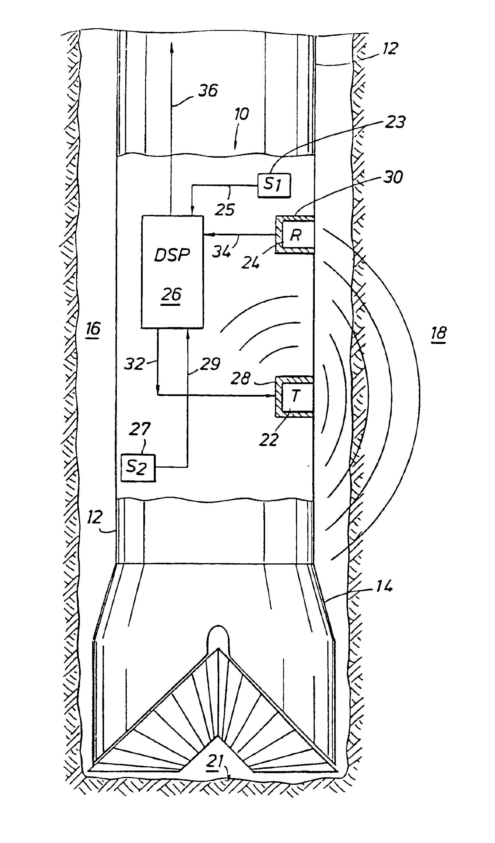
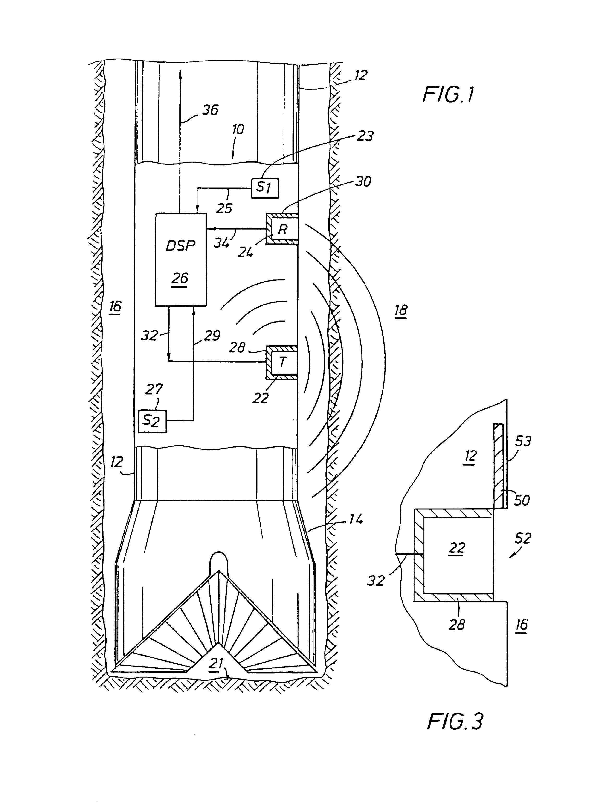
Depending upon whether the borehole 16 or formation 18 characteristics are to be measured, the processor 26 is programmed with the transmitter noise propagating through either the borehole 16 or formation 18 as compressional waves, and its corresponding propagation factor in order that the preferred signal may be determined by eliminating the compressional wave noise propagating along and through the tool body and through either the borehole 16 or formation 18. The mud, borehole 16 and formation 18 properties are incorporated into the propagation factor whenever a noise signal propagating through the borehole 16 or along the interface between the borehole 16 and formation 18 must be determined. Whenever the noise signals propagate through the tool body only, the propagation factor may be analytically determined or preferably by experimentation using a noise measurement sub 60 (FIG. 4) without regard to the drilling fluid (mud), borehole 16 and formation 18 properties. Similarly, the...

example 2

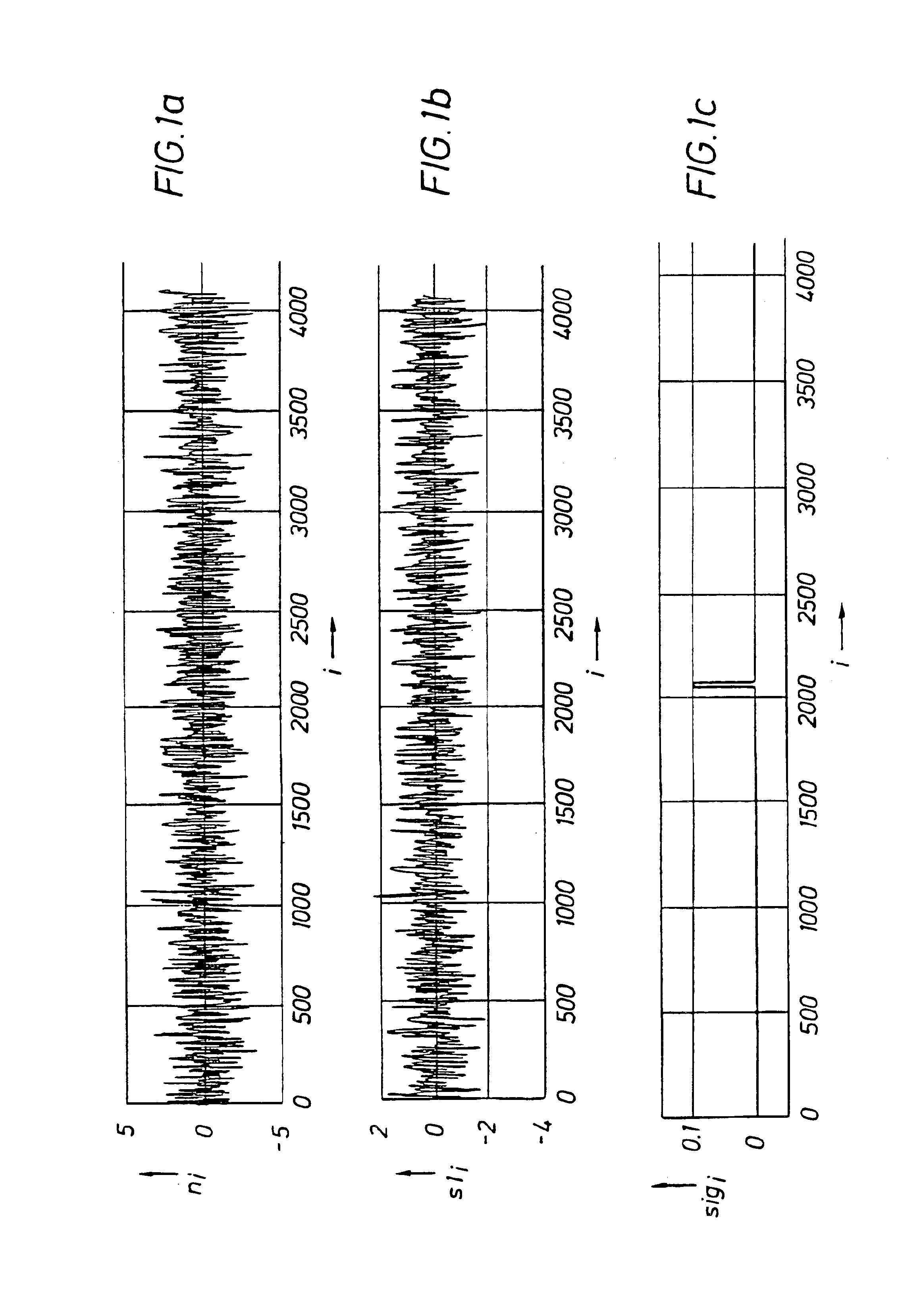
Typically, multiple different noise signals propagating from the same direction are present at the receiver 24 or, alternatively, the noise signals propagate toward the receiver 24 from opposite directions. In either case, an additional second sensor 27 is required in order to determine the noise signal at the receiver 24. In FIG. 1G, a process diagram is shown for simplifying the process carried out by the processor 26. In the following example, a noise signal propagates from the drill bit 14 up the drill collar 12 into the tool body 10 and a noise signal propagates from above the drill collar 12 down into the tool body 10 from precessional movement of the drill collar 12, or from any other cause. The noise signals are n1(t) and n2(t) originating at different points above and below the tool body 10. The first and second sensors 23 (p1) and 27 (p2) are shielded from the acoustic signals traversing the formation 18, and the receiver 24 (p3) is in acoustic communication with the acous...

example 3

If the particular noise signals to be eliminated propagate as compressional waves through the borehole 16 or leaky-p, tube and / or pseudo-Rayleigh waves at the interface between the borehole 16 and formation 18, then a determination of these particular noise signals must be determined using another method generally depicted by the process diagram in FIG. 1H.

Since sensors are not available which can directly detect a particular noise signal propagating in the borehole 16 and the first and second sensor 23 and 27 are isolated from any acoustic signals outside the tool body 10, the first and second sensors 23 and 27 are positioned to detect noise signals propagating through the tool body 10 as compressional wave noise which are used as a reference to approximate the noise signals propagating outside the tool body 10 in the borehole 16, for example, as from the drill bit. The method explained in EXAMPLE 2 above may be used to determine one or more determined noise signals propagating in ...


PUM


Abstract

An apparatus (10) and method are disclosed for eliminating a noise signal from at least one source during an acoustic measurement of a subsurface geological formation or borehole. The apparatus (10) includes a longitudinal body for positioning in the borehole and a transmitter (22) supported by the body for transmitting acoustic signals into the formation and borehole. A sensor (23), substantially isolated within the body, is used to detect one or more noise signals and a receiver (24) is carried by the body for receiving acoustic signals traversing the formation and borehole, and for receiving one or more noise signals. A processor (26) is connected to the sensor (23) and receiver (24) for processing the acoustic signals and noise signals coupled from the receiver (24) and the noise signal coupled from the sensor (23) into a preferred formation or borehole signal by determining the noise signal received at the receiver (24) using the noise signal received in the sensor (23) and a propagation factor for the noise signal between the sensor (23) and receiver (24). The determined noise signal is used to identify and eliminate the noise signals from the acoustic signals traversing the formation and borehole.

Description

FIELD OF THE INVENTIONThe present invention is directed to an improved acoustic downhole logging apparatus and method for canceling unwanted acoustic noise received during the measurement of borehole and formation characteristics while drilling. More particularly, the present invention relates to a measurement while drilling (“MWD”) acoustic tool that eliminates unwanted acoustic noise propagating through the formation, borehole and / or tool body from the acoustic signals received by a receiver in the MWD tool, thus creating an improved signal indicative of various properties of the formation or borehole.BACKGROUND OF THE INVENTIONAcoustic logging tools for measuring various formation properties adjacent a borehole are well known. Measurement of subsurface geological formations may be taken by wireline logs after the well has been drilled or by MWD tools during the drilling of a well, sometimes referred to as an earth borehole. In either application, bulk porosity and elastic propert...

Claims


Application Information

Patent Timeline
Patent Type & Authority Patents(United States)
IPC IPC(8): G01V1/48G01V1/40
CPCG01V1/48
Inventor RODNEY, PAUL F.
Owner HALLIBURTON ENERGY SERVICES INC
Why Eureka
Try Eureka