Key identification system

a key identification and key blade technology, applied in the field of key identification systems, can solve the problems of inability to determine the shape of the key blade surface, inability to extract all the information about the master key needed, and inability to effectively operate the corresponding lock

Inactive Publication Date: 2005-01-04
THE HILLMAN GRP INC
View PDF25 Cites 70 Cited by
  • Summary
  • Abstract
  • Description
  • Claims
  • Application Information

AI Technical Summary

Problems solved by technology

For example, the key owner would need to replace a key after the key has undergone significant use and the cuts and notches on the key blade have worn to a point where the key can no longer effectively operate the corresponding lock.
However, information about the shape of the key blade surface, such as the location and depth of any grooves or millings, cannot be determined from the profile of the master key.
Thus, the back lighting process alone is unable to extract all of the information about the master key needed to identify the key.
Key identification machines that identify a key with the light striping and back lighting processes are typically complex machines as they must include the moving parts and multiple lighting sources needed to both back light and light stripe the key blade.
In addition, imperfections or dirt on the surface of the key blade can result in glares or shadows under the harsh light of a laser generated light stripe.
These glares and shadows are captured as part of the camera image of the light stripe and can reduce the accuracy of the key identification process.
Another problem with known light striping machines is that the master key must be accurately positioned with respect to the light stripe to obtain an accurate identification of the master key.
Any other positioning will result in a distorted non-linear image.
If the alignment of the key is too far off from perpendicular, the distortion of the non-linear will prevent an accurate identification of the key blank.

Method used


Image

  • Key identification system
  • Key identification system
  • Key identification system

Examples


Embodiment Construction

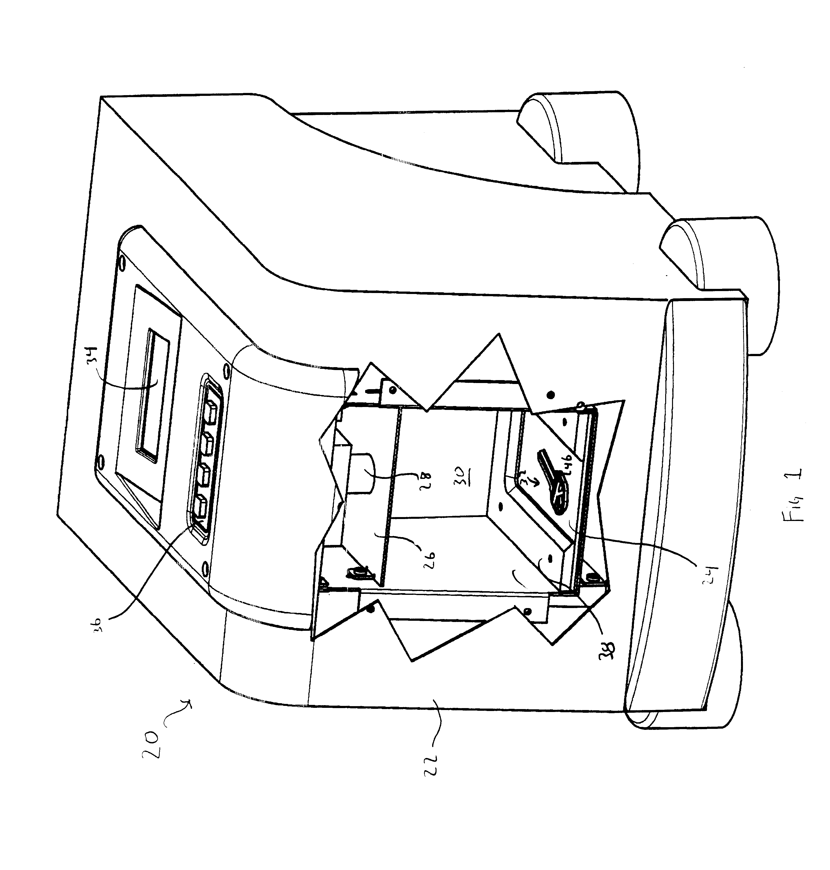
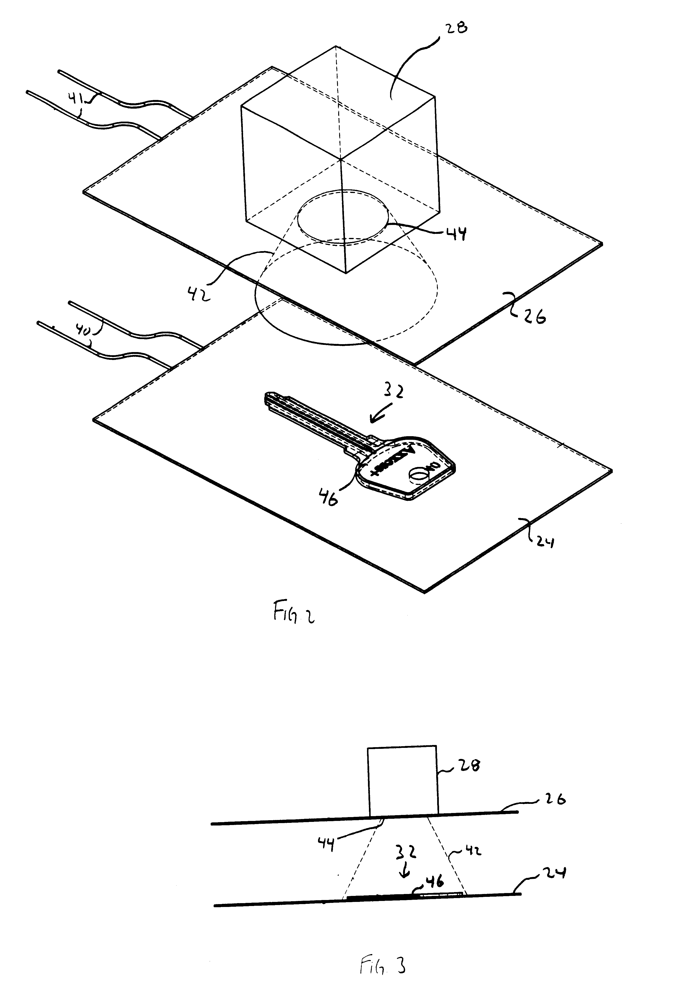
Reference will now be made in detail to the presently preferred embodiments of the present invention, examples of which are illustrated in the accompanying drawings. Wherever possible, the same reference numbers will be used throughout the drawings to refer to the same or like parts. An exemplary embodiment of a system for identifying a master key according to the present invention is shown in FIG. 1 and is designated generally by reference number 20.

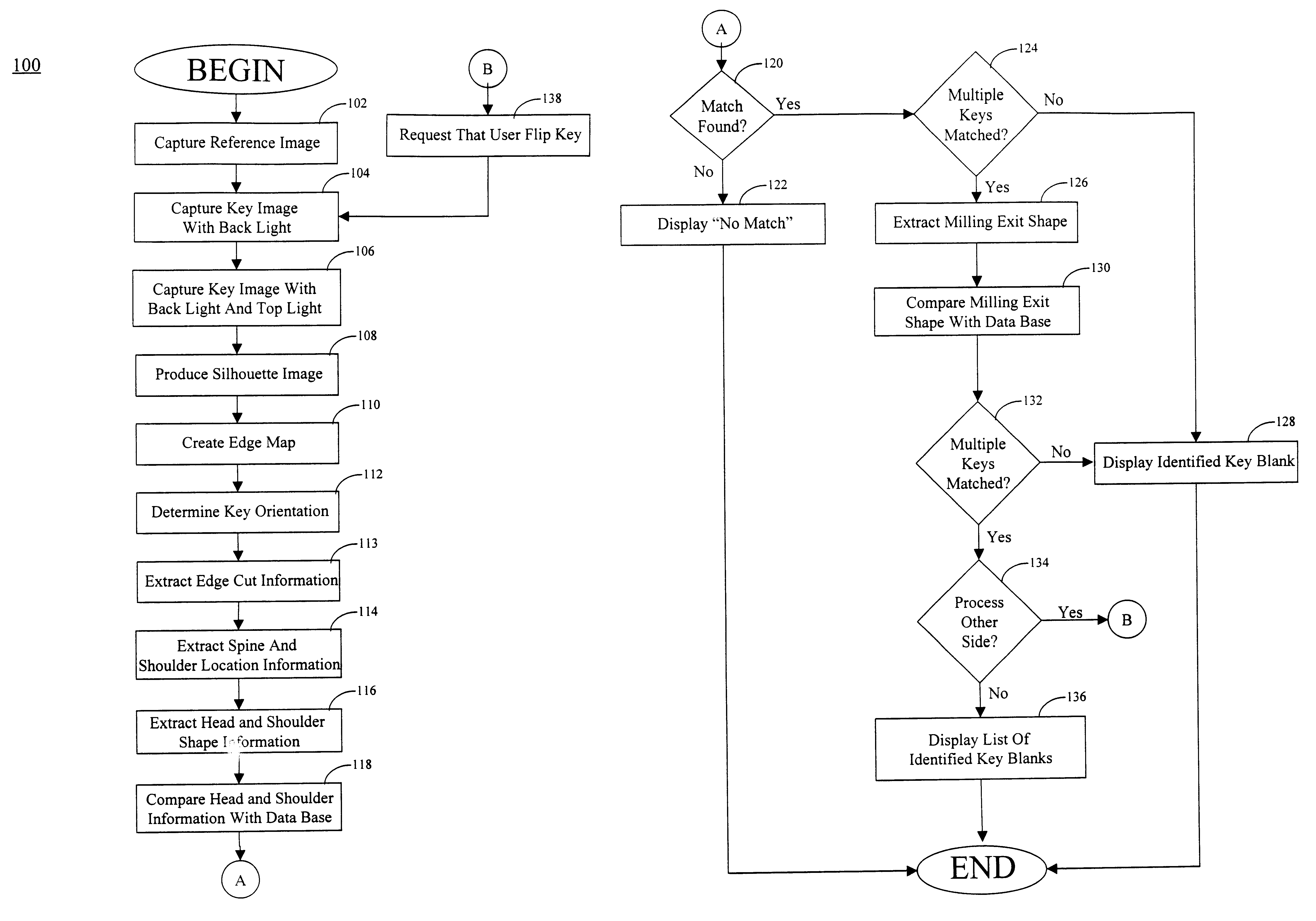
Key blanks are made in a variety of sizes and shapes, each of which is configured to ultimately operate a particular type of lock. To identify the key blank corresponding to a master key, the master key must be analyzed to obtain identifying information about the master key that will uniquely identify the corresponding key blank.

FIGS. 6a, 7a, and 8a illustrate several exemplary master keys. For purposes of simplicity, the master keys are illustrated without a bitting pattern. As shown, each master key 32 has a head 64, a shoulder area 7...


PUM


Abstract

A system for identifying the key blank corresponding to a master key is provided. The system includes a first luminous surface and a second luminous surface. The second luminous surface is disposed opposite the first luminous surface such that the master key is disposable therebetween. The first and second luminous surfaces are operable to generate an image of the master key. A receiver is provided to capture the image of the master key. The system also includes a control having a memory that stores information on a plurality of key blanks. The control is operable to identify the key blank corresponding to the master key based on the image captured by the receiver.

Description

BACKGROUND OF THE INVENTIONThis invention generally relates to a system for identifying a key. More particularly, the present invention relates to a system for identifying the key blank that corresponds to a master key.There are many circumstances in which a key owner may desire to obtain a copy of a key. For example, the key owner would need to replace a key after the key has undergone significant use and the cuts and notches on the key blade have worn to a point where the key can no longer effectively operate the corresponding lock. A key owner may also desire to create a duplicate key to replace a lost key or simply to obtain an extra key.To reproduce a key, the type, or style, of key blank used in the master key must be identified from the numerous types of key blanks available in the market. In addition to identifying the appropriate key blank, the cuts, or notches, in the blade of the key may be identified. After the key blank and the key cuts are identified, a key blank corre...

Claims


Application Information

Patent Timeline
Patent Type & Authority Patents(United States)
IPC IPC(8): B23C3/35B23C3/00G06K9/20G06K9/00E05B19/00G06V10/145G06V20/66
CPCB23C3/35G06K9/2036G06K9/00B23C2235/41E05B19/0011G06V10/145G06V20/66E05B19/00G06F18/00
Inventor CAMPBELL, JOHNHEREDIA, GEORGEMUELLER, MICHAEL A.
Owner THE HILLMAN GRP INC
Why Eureka
Try Eureka