
Flexure life estimating method, wire harness designing method and program thereof

a technology of flexure life and wire harness, applied in the direction of mechanical means, instruments, force/torque/work measurement apparatus, etc., can solve the problems of difficult to fully take the flexure performance of wire harness into consideration, the calculation process load imposed on the computer becomes extremely high, and the calculation period is long. , to achieve the effect of shortening the development period of cars, reducing the calculation processing load of the computer, and being easy to carry

Inactive Publication Date: 2005-01-04
SUMITOMO WIRING SYST LTD +1
View PDF4 Cites 15 Cited by
  • Summary
  • Abstract
  • Description
  • Claims
  • Application Information

AI Technical Summary

Benefits of technology

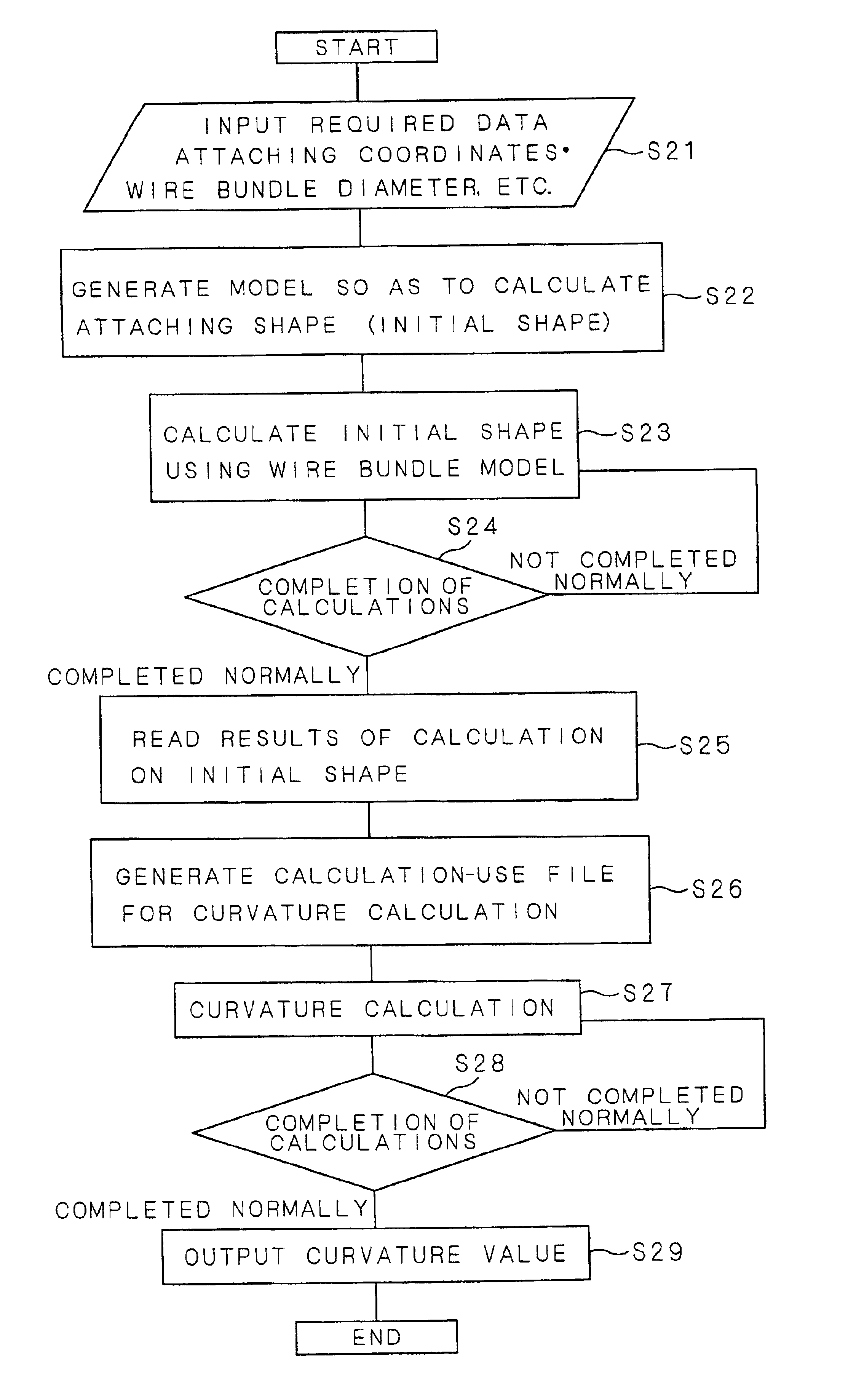
In accordance with this aspect, when a stress of a wire bundle formed by binding a plurality of wires is stress-analyzed based upon the finite element method, it is a rule that, originally, three dimensional analyses are carried out by using individual wires as discrete infinite elements; however, in the present preferred embodiment, the individual wires are not modeled three-dimensionally as discrete structural components, but simplified them into a virtual pseudo-single wire so as to determine the entire shape; therefore, in order to calculate the initial shape and the final shape, by carrying out modeling and calculations not based upon physical properties derived from the actual construction of wire bundle, but based upon the corresponding diameter and bending elasticity of virtual single wire, it becomes possible to greatly simplify the physical properties of wire bundle and also to calculate the resulting values. Consequently, it is possible to obtain an estimated value of flexure life that is closely approximated to the actual flexure life. Therefore, upon calculating an estimated value of flexure life through finite element method (matrix stress analyzing method) by using a computer, it becomes possible to reduce the load imposed on the computer, and also to quickly converge the estimated value.
The other objective of the present invention is to provide a flexure life estimating method of a wire harness that is applied to a case in which at low temperatures, the inner conductor section has a disconnection prior to the occurrence of a crack in the insulating layer, and that can estimate the flexure life efficiently.

Problems solved by technology

In this case, it is difficult to completely take the flexure performance of a wire harness into consideration from the initial designing stage.
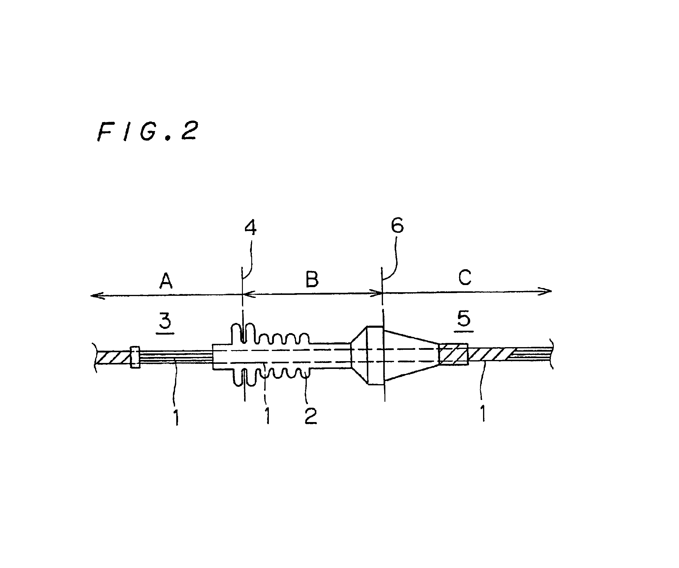
As described above, when a wire bundle in a grommet is analyzed by using the finite element method, the load of calculation processes imposed on a computer becomes extremely high, resulting in a disadvantage of a long period of time required for calculations.
Moreover, the process for dividing the individual structural members such as the grommet and the respective wires of the wire bundle by using finite element meshes forms an extremely time-consuming process.
In general, at low temperatures including cold temperatures, an insulating layer (coating material) such as PVC becomes susceptible to cracks (coat cracks) due to fatigue fracture caused by repeated bending processes on the insulating layer.
However, the above-mentioned proposed example is a method for finding the flexure life, under states where disconnection is mainly caused by cracks on an insulating layer, and the flexure life is found based upon the number of bending processes of the insulating layer up to disconnection; therefore, it is difficult for this method to estimate the flexure life under states where disconnection occurs in the conductor section (core line) with no cracks being generated on the insulating layer.
However, the proposed example fails to effectively estimate the flexure life in the case when the inner conductor section has a disconnection prior to the occurrence of a crack on the insulating layer at low temperatures.

Method used


Image

  • Flexure life estimating method, wire harness designing method and program thereof
  • Flexure life estimating method, wire harness designing method and program thereof
  • Flexure life estimating method, wire harness designing method and program thereof

Examples


embodiment 2

{Preferred Embodiment 2}

The above-mentioned first preferred embodiment has discussed a method of estimating the flexure life that is applied to a case in which at low temperatures, cracks occur in the insulating layer serving as a coating portion prior to rupture of an inner conductor portion to cause a stress that is locally applied thereon, resulting in a disconnection in the inner conductive portion.

However, at normal temperature, in the case when a halogen-free resin material, PE, etc., that have very little temperature dependency are used as an insulating layer forming a coating material, or even in the case when an insulating layer such as PVC that has a temperature dependency is used, if these wire harnesses (wires or a wire bundle) are repeatedly bernt, a conductor portion, which forms an inner core line, sometimes has a disconnection prior to the occurrence of cracks due to fatigue fracture of the insulating layer. Therefore, at normal temperature, the disconnection of wire...


PUM

PropertyMeasurementUnit
inner diameteraaaaaaaaaa
curvatureaaaaaaaaaa
bending modulusaaaaaaaaaa

Abstract

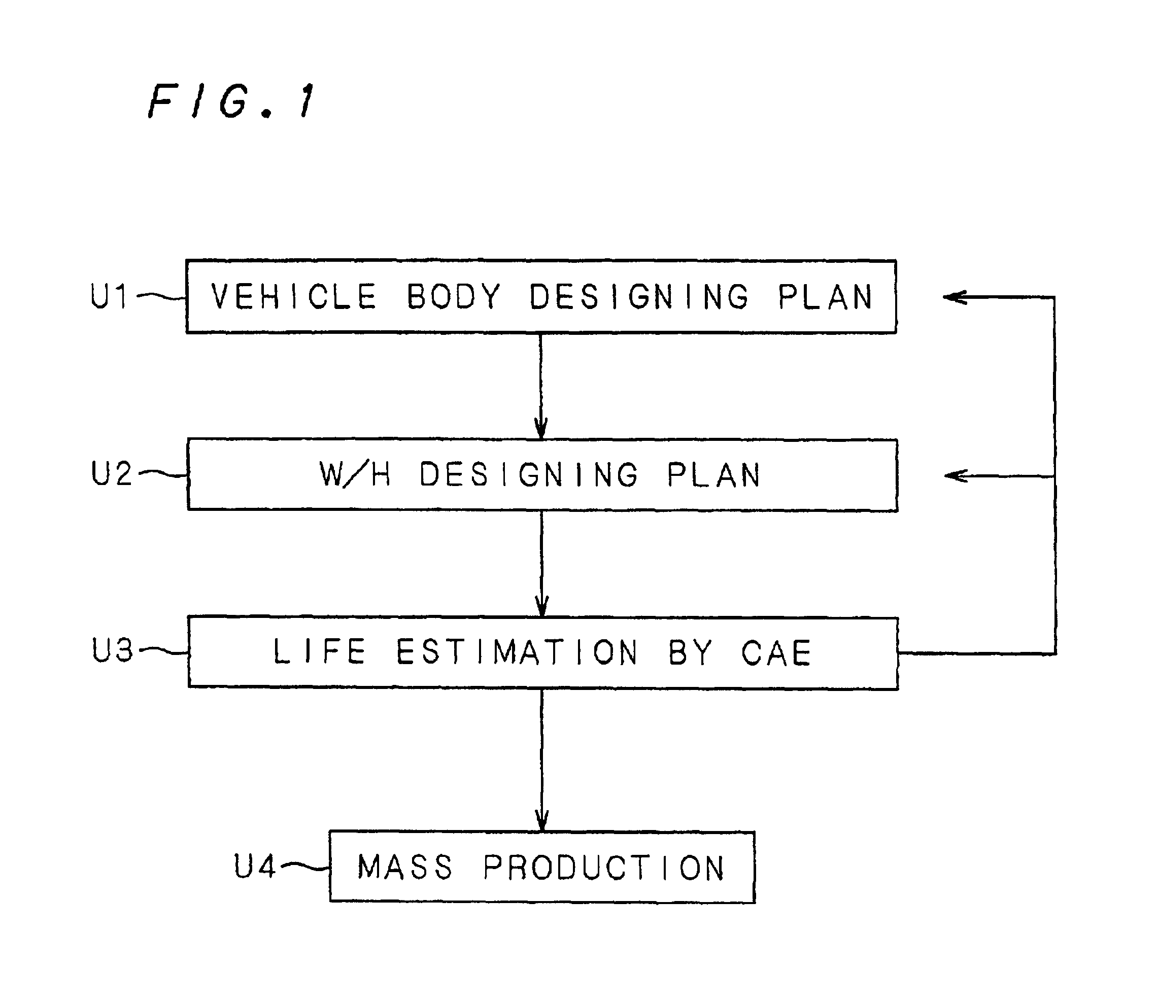
Diameters and the number of respective wires are inputted, and a diameter of a virtual wire formed by converting a wire bundle to a model through a predetermined arithmetic expression derived from rule of thumb, and based upon this, a flexure life estimating process of the virtual wire is carried out. It is possible to easily estimate the flexure life and also to estimate the flexure life and obtain the results immediately after an application subject and a wire harness to be placed have been designed; thus, it becomes possible to shorten the developing period.

Description

BACKGROUND OF THE INVENTION1. Field of the InventionThe present invention relates to a wire harness designing method for designing a wire harness that is placed on a desired application subject and also to techniques related thereto, and more particularly concerns a wire harness flexure life estimating method and techniques related thereto which estimate the flexure life of a wire bundle up to disconnection due to repeated bending processes, the wire bundle being formed by binding wires, each having a conductor line coated with an insulating layer, and used for supplying electric signals and power from a power supply of a car, an industrial apparatus and an electric or electronic apparatus attached thereto.2. Description of the Background ArtAs conventionally known, many wires or wire bundles, each formed by binding a plurality of wires (in this specification, wires and wire bundles are generally referred to as “wire harnesses”), are used in cars and industrial apparatuses. Some of ...

Claims


Application Information

Patent Timeline
Patent Type & Authority Patents(United States)
IPC IPC(8): G06F17/50G01N3/00G01N3/02
CPCG06F17/509G06F17/5095G06F17/5018G01N2203/0023G01N2203/0073G01N2203/0216G06F2217/36G06F2113/16G06F30/18G06F30/23G06F30/15
Inventor KAWAKITA, YUKIINOUE, TAKUYAKAWABE, HITOSHIONOUE, HISAYOSHIFURUSYO, MASARUOHUCHI, KOUJIKAJI, MIKIO
Owner SUMITOMO WIRING SYST LTD
Learn More